
I have been using Civil 3D since it first came out in 2005.
But I have also been using CAD in the civil discipline since 1995 (I know, I’m old :-)!
Over these years, I have compiled MANY tips, tricks, workflows and Civil 3D tutorials to make using it in the civil discipline easier and more fun.
In this article, I will go over those top 20 tips, tricks, and workflows.
So, let’s get started!
Tip 1: Set Your Coordinate System in Your Template
To begin any project using Civil 3D (just like any other project using CAD), you always start with a template.
In the civil engineering world, we are typically working in a state plane coordinate system.
I’ve seen many a user set this EVERY time they start a new file. Instead, you can simply set it in your template.
Navigate to the Toolspace > Settings tab, right-click on the name of your template, and choose Edit Drawing Settings from the context menu.
Tip 2: Expand a Category of Styles
There are times when you want to see all the styles in a category or even the whole drawing.
To easily do this without clicking the expand button for each category, simply click the category you want to expand (or the drawing name), and press CTRL + SHIFT + → or, CTRL + SHIFT + ← to collapse a category.
Tip 3: Reference text
Let’s say you want to see the elevation of a profile that is in a different alignment.
This, and other referenceable objects can be accomplished within a label style.
In the example below, I have already created a reference text component that will reference another alignment’s name, and I am adding the alignment profile elevation.
Notice that after I create the profile reference text, it will update it as it goes along the alignment.
Tip 4: Changing Profile Station and Elevation Easily
To easily change a profile’s station or elevation, simply make sure that Dynamic Input is turned on, and use AutoCAD’s dynamic input functionality to change either one.
Don’t forget the AutoCAD trick to toggling between fields… press TAB on the keyboard.
Tip 5: Transparent Command – Station Offset
There are many times when you want to place a simple AutoCAD object (or even using some sort of Civil 3D functionality), where it relates to an alignment.
The Station Offset (‘SO in the command line) transparent command solves this problem.
A transparent command runs even when another command is active. Essentially, you don’t have to exit a command to run the transparent command.
Below, I am placing a yard drain block (using the INSERT command) based on a station offset.

Tip 6: Seeing Max Stage of a Pond in Profile View
When designing a new road, you will need a pond.
To make sure that your road doesn’t go below this elevation, you can draw a line at the max stage of the pond.
Below, I am using the Profile Station & Elevation Transparent command to draw the max stage of my pond with a line at elevation 147.65.
Tip 7: Getting the Floodplain Elevation
When looking to see if your project is in a floodplain, one of the first steps is of course getting the linework into CAD.
Many agencies provide GIS .SHP files that you can bring into CAD. But once in CAD, you’re only halfway there.
You now need to get the average elevation from the linework to see if you need to provide a floodplain compensation pond if your project is filling in the floodplain.
To get this elevation easily, simply make a feature line out of the linework, assign elevations from your surface, and then take all the elevations along the linework into Excel, do some manipulation to only get all the elevations, and get the avg.
You now have the elevation of the floodplain area.
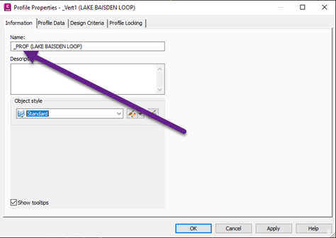
Tip 8: Making Sure the Proposed Profile is Used for Corridor Modeling
Whenever you create a corridor, many users simply keep clicking Next, Next, Next, and don’t even check to see if they are choosing the correct surface for the corridor model to daylight too.
To make sure that your proposed profile gets automatically selected when you create your corridor, add the “_” in front of it so that it will always appear at the top of the list.
This will also ensure that you always pick the proposed profile as it will be the only one with the underscore.
Tip 9: Getting an Exact Pipe Length (with the help of AutoCAD)
When designing pipes, you sometimes want the EXACT length from toe-to-toe so that it makes it easy for the contractor to order pipe as sometimes they come at a standard length.
For example, RCP (Reinforced Concrete Pipe) comes in 8’ “sticks” so you should always make sure that your toe-to-toe length is in an 8’ increment.
To easily automate this, simply draw an AutoCAD line at the length you need, draw the pipes in the drawing, and grip edit the structures to the correct location.
Don’t forget, if you need the length to come from a specific location on the structure, you have the base Point option with the AutoCAD grip editing functionality.
Tip 10: Easy Targeting
When doing roadway modeling, you will inevitably have to do some targeting.
To make life easy when targeting, what you should do is create layers ONLY used for targeting specific features of your corridor model (e.g., a ditch bottom, edge of the shoulder, etc.).
This will make it super-easy to target subassemblies by simply picking the layer.
In the example below, I have a subassembly that is targeting a feature line for the ditch bottom.
If I put this feature line on a unique layer, it will make it extremely easy to choose it by the layer in the Target Mapping dialogue box.
Also, if the entity changes or I add additional objects on that layer later on in the design, Civil 3D will automatically find it as it dynamically looks for any entity if using the layer method of targeting.
Tip 11: Targeting the Top of a Pond
Many times, when doing roadway design, you will need a pond in a specific area of the road, and you need to know where this top-of-pond feature will be as it relates to your road.
So, how do you do this?
First, in your assembly, you add a horizontal conditional to activate it where needed and attach a LinkSlopeToElevation subassembly to it.
All you have to do is enter the value of the top of the pond in the elevation field and have that region of the corridor model use this conditional.
Now, to extract the feature line so that you can connect it to your top of the pond, simply use the Feature Lines from Corridor tool.
To make it easy for extraction, make sure you give the point code of the LinkSlopeToElevation subassembly a unique value, such as pond.
Tip 12: “Locking” a Feature Line to a Surface
When doing site design, you use a lot of feature lines.
Well, what if your feature lines need to “tie in” to a road?
What if the road changes, you would of course want the feature line tying into the road to update automatically.
This can be accomplished using the Relative to Surface option for any feature line.
What’s cool about the functionality is that if the feature line doesn’t go over the surface you want it to be relative to, you can control it with the standard feature line tools.
In the example below, I have a feature starting at zero elevation.
I then make it relative to the proposed road surface, and then independently change an elevation point to control the drainage.
Tip 13: Using ONE Assembly for a Corridor Model
With Horizontal conditionals, you can have one assembly, and turn on/off various parts of the design with additional conditional subassemblies.
First, start out with a Not Found Horizontal conditional.
This will ALWAYS work unless you target it.
This conditional should have the standard typical subassemblies you normally need per your design.
Then, to turn on different design scenarios, you first target the not found (shutting it off) and target the conditional that you want to turn on.
This simply requires that you have some sort of linear feature that is offset from the alignment (a polyline).
In the example below, I am adding a conditional that will provide a fill slope.
Again, as I need additional design scenarios, I simply add another conditional.
Tip 14: Easily Adding Corridor Transitions
New in Civil 3D 2023 is the ability to add transitions… WHEREVER!
Prior to this functionality, you would add offsite alignments with a widening taper, or polylines that followed let’s say a meandering sidewalk.
Now, there is a specific tool to create transitions from any of the subassembly offsets, really powerful!
In the example below, I am going to add a transition for my inside boulevard with the sidewalk subassembly.
Tip 15: Easily Finding Your Assemblies
Whenever you create assemblies in a model file, you should create an easy way to find them.
I always recommend to users make a nice big rectangle with a global width before they begin any assembly creation and put some nice BIG text at the top that makes it easy to find.
In addition to this rectangle, you can also use AutoCAD text fields to easily see the name of your assembly in the drawing.
This is especially useful if you have a lot of assemblies for a complex project.
And don’t forget, if all else fails, look to your Prospector tab to find the assembly you want to edit.
Tip 16: Dynamic Input to the Rescue
I hear this all the time from users, “I hate Dynamic Input, it gets in the way, so I turn it off.”
I always calmly recommend, learning to deal with the “get in the way part,” because there is SO MUCH additional functionality that is so useful, especially as it is very well integrated into many of Civil 3D’s workflows.
Below are just some example uses of Dynamic Input (and don’t forget the Profile Station and Elevation tip above!).
Tip 17: Letting the Corridor Control Your Site
When developing a site, sometimes it’s hard to envision or see where your site will need to go regarding the elevation if you’re coming from an existing road.
Instead of worrying about it, or doing some hand calcs to figure out elevations, simply let the corridor do it for you.
In the example below, I made a feature line of my centerline coming from the existing road, into the site, and I made a corridor from the feature line.
Remember, you don’t have to have an alignment/profile to create a corridor, a simple feature line will do the trick.
I made a surface from the corridor, and then I take my “dumb” AutoCAD polylines and make them feature lines, relative to the road, and BAM, I have my starting elevations.
The best thing about this is that if I change the road, the feature line elevation changes as well!
Tip 18: Slope Labels EVERYWHERE!
One of the hardest things for new designers to learn and remember to check is the grading between the various parts of your design.
What I tell users to do immediately after they have created a combined proposed surface is to copy slope labels EVERYWHERE.
This will make it extremely easy to see if you are exceeding a grade that you shouldn’t.
The great thing about doing this is that you can simply create one, and then copy it around throughout your design.
Also, while we’re talking about surface slope labels, I recommend that you also label your feature lines. This way, you can REALLY see what the grades are doing.
Tip 19: Globally Renaming Your Feature Lines
When doing site design, I recommend to EVERYONE, no matter how fast you need to get a site done, make sure you’re not only naming your feature lines appropriately, but you are also putting them on the correct layer.
See the next tip as to how you can control the look of a feature line, simply by putting it on the correct layer.
If you forgot to name them, don’t fret.
Civil 3D provides a way to globally rename feature lines.
In the example below, I am making sure that all my edges of pavement have the prefix EP.
Tip 20: One Feature Line Style to Rule Them All
There are many engineering firms that think they need to create a feature line style for all features that may exist in a project.
This list can get large if you think about every feature in the world of civil engineering.
In my opinion, for site design, you really only need one feature line style for all feature lines and let the layer control how it looks.
If you do corridor modeling or project feature lines to cross sections or profiles, then yes, you will need feature line styles to control how the feature line projects or looks in the corridor model.
Below, I show you how to make one feature line style, to rule them all.
Notice how all of the feature lines’ properties change immediately as they are taking on the properties of the layer that they are on.
Conclusion
So these are my collected Civil 3D tips that I recommend you should use as well.
If you have a tip that can be included in this list then let me know in the comments area down below.
Leave A Comment