
IN THIS ARTICLE
Making and using AutoCAD Dynamic Blocks
Dynamic blocks in AutoCAD are like blocks on steroids.
In a regular AutoCAD block, you can use one base point and maybe rotate or scale it and that will be almost all the flexibility it has to offer.
But in a dynamic block, you can stretch it, change its shape, change it entirely to a different type and a lot more.
As an example here is the dynamic block that we will learn to make in this article.

Essentially using the single dynamic block we will make the pipe diagram where the pipe length can be changed, the direction of flanges can be changed, T and elbow joints can be added anywhere and a lot more.
The final block in our example will look like the following image, here it is made with just one single block used several times over in this drawing.
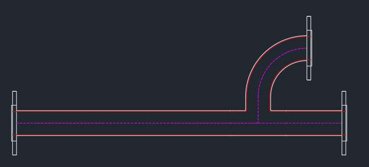
In this article, I will show you the step-by-step method of making the pipe-fitting dynamic block as shown above.
Using this dynamic block you can make as many configurations of pipe fittings as you like.
If you want a video of this tutorial then here it is, if however, you want the text tutorial then keep reading.
So, let’s begin with the simple drawing that will make the building block of this pipe dynamic block.
Starting the dynamic block
I will start with the basic sketch of the different views of the pipe diagram that we want to make.
As shown in the following drawing we will make the front and top view of the flange, then make the pipe and its T and elbow joints.

Once we have these, we are ready to convert them into a real AutoCAD dynamic block.
There are several ways of doing this and I will use a simple method for this but before we do that let’s see what we want the block to look like in the end.
- The pipe should be stretchable so that its length can be changed.
- The front of the flange should be able to rotate so that we can fix it in any direction.
- All these parts of this piping diagram should be made using one single dynamic block.
- The centerline of all the block views should align with one another.
Keeping these conditions in mind we will make the dynamic block, so, let’s get started with the Block command.
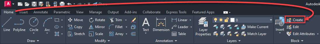
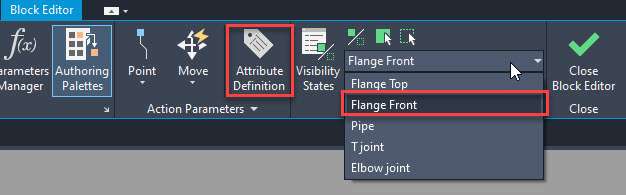
You can type B and press enter to start the block command or you can also click the “create” option on the block panel to start the command as shown in the following image.
Now the block Definition palette will open up.
Select the name of the block from this palette in the Name field, I am using “Pipe block” as the name for this example.
Then click the “Pick point” box and select the centre of the top view of the flange.
Then click the “Select objects” option from the Block Definition palette and select all the objects from the drawing area and press enter.
In the behaviour panel make sure “Allow exploding” is checked and “Annotative” as well as “Scale uniformly” options are not checked.
Finally, click the “open in block editor” option on the lower left corner of the “Block definition” palette and click OK.
Here are all these steps as shown in the following animated image.

The drawing will now open in the block editor and here you can add the dynamic properties to the block.
We will start with the visibility settings in our dynamic block but before we do that, we need to make our drawings manageable by separating them into 5 groups.

Making groups from block drawings
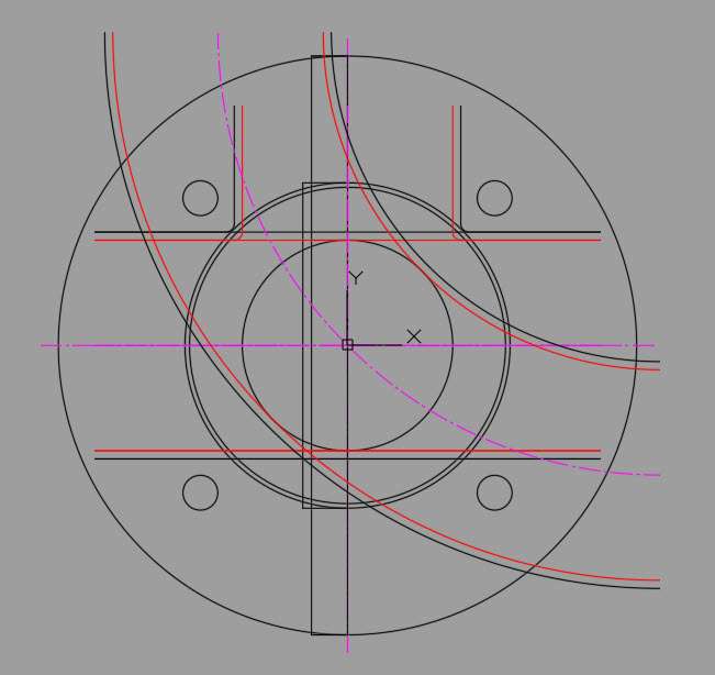
We need to merge all of these separate pipe drawings into one using the visibility parameter and for that, we need to place all of these drawings on top of one another.
This is problematic as this will just make the entire drawing very confusing like the following image.
So, to fix this issue I will convert all of these separate drawings into groups so that all the separate views like Front view, Top view, Pipe, T joint and Elbow joint are easily selectable when working with block editing tools.
Grouping will make selecting these objects easier and then we can select these objects as one unit rather than making a selection of the entire set of lines, circles and other geometries that make up these drawings.
This grouping is a temporary arrangement and after converting everything into a dynamic block we can break these groups.
To start the group command type GROUP and press enter, then select the top view of the flange and press enter key.
This will convert the top view of the flange into an unnamed group and if you select any object from this group the entire top view will be selected.
Similarly, repeat the group command and convert the front view of the flange, pipe, T joint and elbow joint into separate unnamed groups.
Once you are done converting all the separate drawings into separate groups place them on top of one another with the mid or centre point overlapping for all objects as shown in the following video.
Now we are ready to add the visibility parameter to this set of groups.
Adding visibility parameter
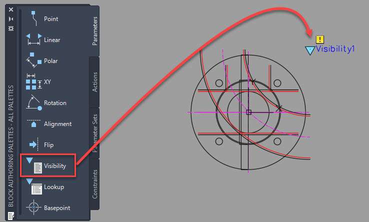
In the Block Editor select the “Parameters” tab from the “Block authoring palettes” then click the visibility parameter and then click at any point close to our cluster of groups preferably at the top right corner as shown in the following image.
If for any reason the block authoring palette is not visible, then type BAUTHORPALETTE and press enter key and the palette will show up.
Now you need to associate this parameter with an action.
The action for the visibility parameter is not available on the Actions tab of the Block authoring palette and rather you will find it on the Visibility panel of the Block Editor tab as shown in the following image.
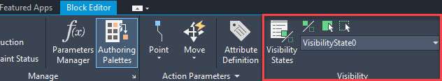
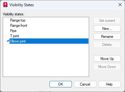
From the Visibility, panel click the “Visibility States” option and then select “VisibilityState0” from the list of visibility states and click the rename button. Rename this default visibility state to “Flange top”.
Click the “New” button and add “Flange front”, “Pipe”, “T joint” and “Elbow joint” visibility states as shown in the following image.
Click OK on the “Visibility states” panel when you are done adding all the visibility states.
Now it’s time to make this visibility states useful.
Select the Flange top visibility state from the visibility states dropdown on the “Visibility” panel.
Now click the “Make invisible” option from the Visibility panel and click on all the groups of objects that are not “Flange top” as shown in the following animated image.

Repeat this process for all the other visibility states.
Essentially, as the next step change the visibility state to “Flange front” then click the make invisible option and click on all the groups of objects that are not “Flange front” and then do the same for “Pipe”, “T joint” and “Elbow joint” visibility states.
After finishing it we need to clean our block by removing the groups that we created earlier as we no longer need them to select the objects as one unit.
Also for the next set of parameters, we need our drawings objects as separate entities rather than as groups.
Cleaning up the dynamic block
To remove the groups, type CLASSICGROUP on the command line and press enter.
Now select the “Include Unnamed” check box and then all the unnamed groups that we created will show up in the list.
Select the groups one by one and then click the “explode” button so that all the groups are removed.
Follow the steps mentioned in the following image to remove these groups.
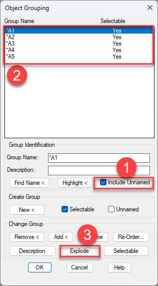
Once all the groups are removed click OK on the “Object Grouping” palette and now we have a clean dynamic block ready for the next step.
Adding Stretch property
After the visibility parameter and action, we need to add the next property in the “pipe” drawing of the dynamic block.
Essentially we want to add the stretch property to the pipe view of the block so that it can be stretched to whatever length we want in either direction.
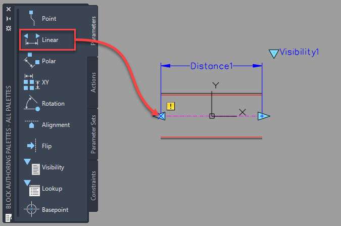
To do this select the “Pipe” visibility state from the Visibility panel so that the pipe part of the dynamic block shows up.
Select the “linear” parameter from the parameters tab of the block authoring palette in the block editor.
Click on the endpoints of the purple centre line of the horizontal pipe and place the parameter above the drawing as shown in the following image.
Now select the Actions tab from the block authoring palette and select the stretch action.
Click on the “distance1” action that looks like a dimension which we created in the previous step and then click on the left endpoint of the purple centerline.
Now make a selection frame that starts at the bottom right corner of the pipe drawing and move it to the top left corner.
Make sure you start the selection box slightly before the end point of the pipe drawing so that all the lines are not completely inside the box rather, they should intersect it as shown in the following animated image.
Then select all the objects making the pipe drawing including the Distance 1 parameter.
Now repeat the same steps but this time make sure you select the right-sided endpoint of the purple centerline and select a stretch frame that starts from the lower left corner and extends to the upper right corner.

And now our pipe is stretchable, and its length can be changed in both directions.
Creating rotation parameter
Now that we have a pipe that can be stretched to whatever length we want let’s look at creating the front view of the flange that can be rotated to any angle.
For that start with the Parameters tab of the “Block authoring palettes” and select the rotation parameter.
Now click at the midpoint of the vertical line of the flange and click on the right side at a 0-degree angle twice.
This will add a rotation parameter that looks like the following image.

Now go to the “Actions” tab from the “Block authoring palettes” and select the Rotate action and then click on the Angle1 parameter then select the entire set of objects that make the front view of the flange including the Angle1 parameter.
Finally, we have a rotation parameter, and the front view of the flange can be rotated about the midpoint.
With this, the dynamic block is now finished and we can test it now.
So, click the “Close Block Editor” green check mark at the top right corner of the ribbon area and click “Save the changes to Pipe Block” in the next prompt.
This will exit the Block editor environment and we are now in the drawing area with our dynamic block.
Testing the Dynamic Block
Now that we have the dynamic block fully prepared and ready for action let’s try it.
Delete everything from the drawing area including any block that is available.
Click the “Insert” option from the “Block” panel of the “Home” tab and then select the block that we just created and place it in the drawing area.
Now select the block and then click the blue arrow that shows up on the top right corner and select the “Flange front” from the list.
Make a copy of this block again and then change the visibility state of this dynamic block to “Pipe”.
Now repeat this process of copying this block and selecting different visibility states to create the pipe drawing as shown in the following video.
With that, we now have an intelligent drawing with dynamic blocks where we can change the pipe length, flange angle and other properties directly using the dynamic block feature.
Making AutoCAD dynamic block with Attributes
So far we have a functional dynamic block which is already working great but now we will make it more useful by adding attributes to the different views of the dynamic block.
For that, we need to edit the dynamic block.
Select any view of the dynamic block from the drawing area then right-click and select “Block editor” from the context menu and now we are back in the block editor where we can edit the dynamic block.
In this case, we will add tags for the pipe views using attributes so that they can be easily identified.
Essentially we will use P1, P2, P3 etc for pipes and similarly T1, T2, T3 etc for T joint and so on.
Adding Attributes
From the visibility panel of the block editor environment select the “Flage front” view as shown in the following image.
Now only the Flange front view will show up in the block editor.
Select the “Attribute Definition” option from the “Action Parameters” panel of the block editor tab as shown in the image above.
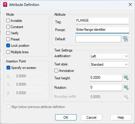
The “Attribute Definition” window will now open up with several options. Uncheck all the boxes from the “mode” panel except the “Lock position” and then add the following values.
Tag: FLANGE
Prompt: Enter flange identifier
Levale the “Default” section blank and set the text justification to “Left”, style to “Standard” and text height to the default value or a value that will make your text look normal in size when compared with the block.
I am using 0.2 as the text height for this example, finally, your “Attribute Definition” window should look like the following image.
Now click OK to close the “Attribute Definition” window and click click anywhere close to the block to add the attribute tag.
We now have an attribute associated with our Flange front view of the dynamic block.
You can repeat the process for other views of the dynamic block as well and create several attributes associated with different views of the dynamic block.
In my case I am adding the attributes to pipe, T joint and Elbow joint views of the dynamic block as well.
After adding all the attributes to different views simply click the close block editor check mark on the Block editor tab and click to save the changes and return to the model space of the drawing.
Using and modifying attributes
Now that we have the dynamic block with attributes it’s time we use it in our drawing.
If you’ve already used a dynamic block in your drawing without any attribute then you need to sync it first before the attributes can be used.
To do that type ATTSYNC and press enter key.
Now press enter key again and then select the block from the drawing that you want to sync.
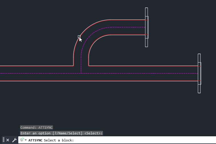
In my case, I will select the Flage front view of the dynamic block and then press enter again.
This will sync the Flage front view and now you can add an attribute on that view but you need to repeat the ATTSYNC command for all the other views as well where you have added attributes in the previous step.
For my example, I am using the ATTSYNC command for Pipe, T joint, and Elbow joint as well.
Now we can modify the attributes for all the views of the dynamic block separately.
Select the block for which you want to modify the attribute and then right-click and select “Edit Attribute” from the context menu.
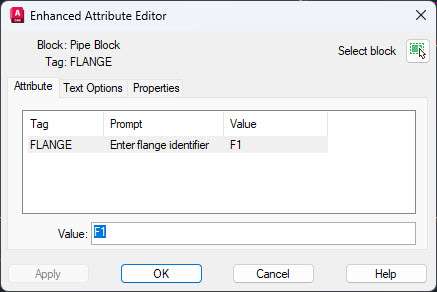
In the “Enhanced Attribute Editor” add the value that you want, I am adding F1 for the first flange and then click OK.
Repeat the process for all the other dynamic block views.
After adding all the attributes my final dynamic block looks like this.

Conclusion
Dynamic blocks of AutoCAD are great for making an intelligent set of blocks that will skyrocket your productivity.
So, whenever you feel like you are using several similar blocks try replacing them with one dynamic block.
Do you use dynamic blocks in your drawings? Let me know in the comments below.
Dynamic blocks in AutoCAD are like magic wands for your designs. They allow you to make quick changes to your designs without having to start from scratch. Imagine being able to adjust the size and orientation of doors or windows with just a few clicks – that’s what dynamic blocks can do for you!
Picture this scenario: you’re working on an architectural design and suddenly your client asks for the door to be moved and resized. In the past, this would have meant redrawing everything from scratch. But now, with dynamic blocks, you can simply grab the door with your mouse and move or resize it as needed. It’s like giving yourself superpowers to make your design process more efficient and hassle-free.
Creating dynamic blocks is a breeze too. With the Block Editor, you can draw your block, set up the parameters you want to control (like size, orientation, or shape), and voila! You now have a block that can be adjusted to fit your design needs.
Dynamic blocks are a must-have for anyone who wants to streamline their design process and save time. Whether you’re working on architectural designs, mechanical parts, or any other type of design, dynamic blocks will make your life easier and help you create better designs in less time. So, if you’re looking to up your AutoCAD game, give dynamic blocks a try – you won’t regret it!
You can stretch meshes or 3d faces. I have made dynamic tray blocks using 3dfaces and it works well. You are correct you can only work(stretch/move/rotate/flip) in the X/Y plane.
Hello Carel,
I have hundreds of blocks – roadway signs, that I wish to use visibility and position parameters for the labels for each block. These parameters will be the same for each block. Is there a way to make a template with these parameters already set, in which I can drop a block into it and then save that block with the visibility and position parameters attached to it?
Hello,
can one such a block be insrted in autocad plant 3d as inteligent part for the catalog?
One static block can be insetted in cata as a stp file…with only connection points added.
thanks
N
Hello Mohamed,
Yes, you can assign block stretch to sides also. Constrain your part before adding it
hi.. how are you
i have one question please
how can i make dynamic block stretch from to side at same time ?