
How to make 2D from 3D drawing in AutoCAD
There are at least two popular methods of converting 2D from 3D drawing in AutoCAD and these methods are using FLATSHOT command and using Layout views.
In this article, I will show you both methods but I will start with the FLATSHOT command that will let you make the 2D drawing directly in the model space.
Using FLATSHOT command
I have also prepared this video to explain this method in detail, but if you prefer the article instead then read on.
This command can create 2D views like top, front, and isometric from a 3D model with just a few clicks directly in the model space.
For explaining this command I will use this sample 3D drawing as shown in the following image, you can make a similar 3D drawing or use your own 3D drawing to follow along.
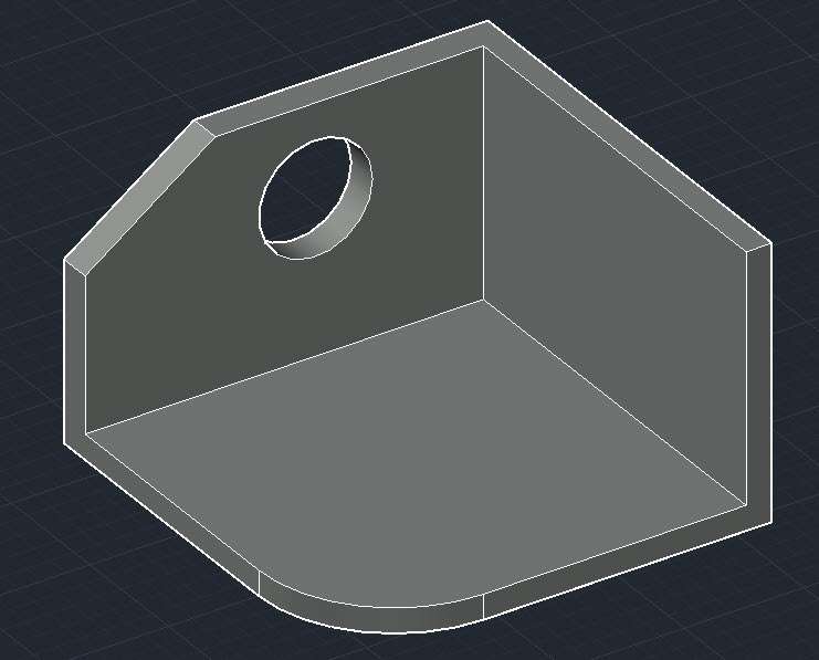
Start AutoCAD and switch the visual style to “Shades of Gray” as shown in the following image so that the 3D model is clearly visible like the part shown above.

Understanding the FLATSHOT dialogue box
Select the FLATSHOT tool from the expanded “Section” panel of the “Home” tab or type FLATSHOT on the command line and press enter.
The “Flatshot” dialogue box as shown in the following image will open, let’s have a look at the options of this dialogue box.
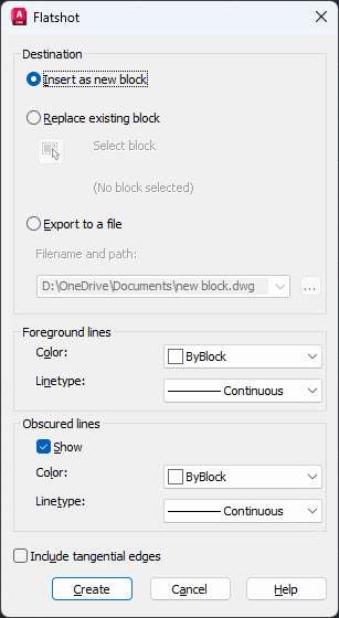
Destination:
The first option in the destination panel “Insert as new block” will ensure that new 2D views generated using Flatshot will be inserted as a block in the current drawing.
The “Replace existing block” option will replace any block which you select with the 2D view created with the Flatshot tool.
The third option “Export to a file” will export the 2D drawing to a new DWG file.
Foreground line:
These are the visible lines which are projected on the Top plane (also called the XY plane) along the current view which you have selected.
You can set the color and linetype of the main 2D view using this option.
Obscured line:
These are hidden lines present in 2D geometry.
If you want to show hidden lines then select the “Show” check box and change the color and Linetype of obscured or hidden lines from the drop-down menu.
Include tangential edges:
The last option is a checkbox mentioned as “Include tangential edges”.
Checking this option will ensure that the tangential edges like fillets are also shown in the drawing, the following image shows the tangential edges clearly.

Now that we know about the options of the Flastshot dialogue box let’s learn how we can use it to make 2D drawings using 3D.
Creating Top View
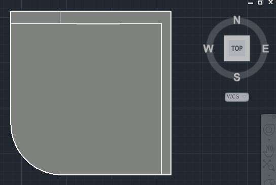
In your View Cube set the current view to TOP so that the 3D part’s top view is only visible.
In my case, setting the view to the Top on the View Cube will make the 3D drawing look like the following image.
Select the Flatshot tool from the expanded section panel of the Home tab or type FLATSHOT on the command line and press enter key.
Select “Insert as new block” in the Destination panel of the Flatshot dialogue box.
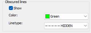
Don’t change the properties of foreground lines and select the “Show” check box in the “Obscured lines” panel then change its color to green or anything else that you want.
Also, change the linetype of obscured line to “Hidden” from the linetype option.
Select the “Include tangential edges” check box and click Create.
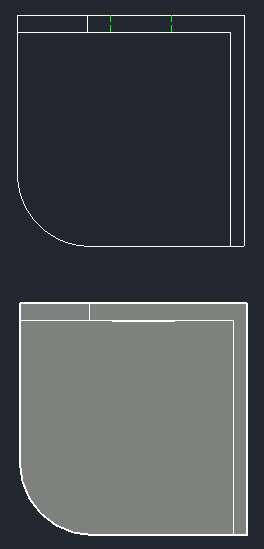
You will see the 2D drawing of the Top view of 3D geometry is now created and it follows the cursor.
Click at a point in the drawing area preferably above the 3D drawing top view and press Enter key thrice to accept all default values.
After adding the views my drawing looks like the following image.
In a similar way, you can make the other 2D views from the 3D drawing.
Creating Front View
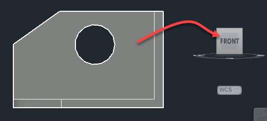
Change your view to Front from the View cube or View drop-down menu so that the 3D drawing looks like the following image.
Again start the FLATSHOT command.
Select all the options from the Flatshot dialogue box just like in the previous example of the Top view and click on Create.
In this case, also the 2D drawing of the Front view will follow the cursor but instead of a clear geometry, it will appear like a line because geometry is created on the top plane and we are on the front plane.
So simply click near the 3D view and press the enter key thrice and the view will be generated on the top plane.
Switch to the Top plane or the XY plane and you will be able to see the front view clearly like the image shown below.
The 2D drawing view generated may not be close to the 3D drawing, so you need to move it closer if it’s created far off.
In this case, I moved it to the respective location like at the top of the drawing and on the right side.
You can do that same once the 2D views are added in the drawing area.
Creating Isometric view
For creating the 2D isometric view from a 3D drawing change your view to SE isometric or any other isometric view which you like.
In my case, the isometric view looks like the following image.

Once again start the Flatshot command then use the same options we used in the previous two examples and place the view created at a location close to the 3D drawing and press enter key thrice.
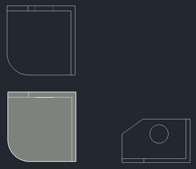
After rearranging all views created so far this is what my 2D drawing views look like.

Now that you know how the Flatshot command can be used to make 2D views from 3D drawings let’s talk about another method that will let you convert 3D drawings into 2D in the layout view of AutoCAD.

Using Layout View to Convert 3D into 2D
This is the method that you should use if you want to use the layout view of AutoCAD to generate the 2D views from your 3D drawings.
For this example as well I will use the same drawing that I used for the Flatshot command.
So, start the drawing and change the visual style to “Shades of Grey” and remove any 2D drawings from the drawing if there are any.
Now switch to the layout view using the “Layout 1” tab on the bottom left corner of the drawing view.
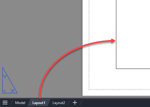
Now a white layout with a rectangular box with your 3D drawing in it will show up, delete this rectangular box.
Now go to the Layout tab and select the “From model space” option from the “Create view” panel as shown in the following image.

AutoCAD may take a few seconds to process this drawing and after a few seconds, the drawing’s front view will show up on your cursor.
Click at a location on the layout to place this front view and then press enter key.
The front view will be added and now you can move your cursor above the drawing to place the top view.
After that move to the left to create the left-side view and move to the top left corner to make the isometric view.
Once you are done making the views press the enter key and AutoCAD will instantly generate the 2D views from your 3D drawings as shown in the following animated image.

Depending on the drafting standard first angle and third angle projection system your view placement may change but more or less it will remain the same as shown in the example above.
Now you can add more details like dimensions and other annotations in this view as well.
One important thing about 2D views created here is that they are linked with the 3D drawing so if you later decide to change the 3D drawing or modify its features the 2D views will change automatically.
Conclusion
As you can see there are two easy methods of converting 3D drawing to 2D in AutoCAD and both are easy and straightforward.
The first method of using the Flatshot command will help you make the 2D from 3D in model space and the second method will help you make it in Layout space.
Let me know in the comments if you are using these methods.
I’ve tried with XY showing in viewport of a 3D model with WCS active/top view/hidden but I keep getting the message “Flatshot operation did not generate any geometry”, any advice?
sir may you please tell how i can take 3d view into autocad already made 2d drawing.
but why when you plot the drawing the object is pixelated?
EXCELLENT LESSON. THANKS DEAR SIR.
Super Tutorial
Thank you so much. I used flatten command before, this one makes it easier.
How can I convert 3D model to a 2D model of drawing
hi i wanna change my creo 3d model to 2d,but i donno how.please help.thanks
Tried to browse the template but couldn’t and it’s showing…
” Command: viewbase
Specify model source [model space/file] : M
Unable to perform request action.
This drawing was last edited with documentation in a newer version of AutoCAD.
Thanks.
How can I change 3D model of drawing to 2D model of drawing
If your sketch is dimensions does the scale stay the same?
Yes, in an orthographic view the dimensions will stay true. They will not in an isometric view.
very useful to beginers
Thank you very much for your great offer
Hi Jaiprakash,
Thank you for your very clear tutorials. However I still stumble into a problem regarding 3D to 2D.
I receive 3D drawings but need to convert them into 2D drawings so they can be used in AutocadLT.
It’s not clear to me how to do this. Do I miss something in my perception?
The reason is we have suppliers who only use AutocadLT.
Good day pandey,
I will like you to assist me in making chemical engineering drawing. .as a beginner..
You tips will be appreciated.
Thank you for this grate offer..
Thanks a lot sir, I could draw 2d drawings which I was struggling for long. But after lot of trouble. I first changed view from View menu on Home tab and that did not work as in every view it was showing X Y plane and I was geiing lines of two view. then I tried from View Cube and got success.
Thanks for your guidance
Hi sir, I would ask you about a few questions. When I make isometric view, why the dimension is not as same as the 2D? Is it how it works? And why dimension in 3D is not flatshooted in 2D? Do I have to redimension all of my shoots?
The dimensions are actual one even in isometric view. In that case, the dimensions are skewed because of viewing angle from which the drawing is made. If you want to keep original dimensions even in isometric view then use 3D drawing and generate its views in the layout. More about this is in this video https://www.youtube.com/watch?v=orIGydXXvVo
Hi Jaiprakash,
I am trying to create a 2D drawing of a 3D object in AutoCAD 15. First, I go to the layout 1 tab at the bottom left and delete the current viewport. Then, I click on layout tab -> Base -> from model space and try to place the base view on the page but I get ‘Move’ in the command box. What am I missing here? I am enrolled in your 2D and 3D practice drawing course and am currently working on the M10 nut and want to create a base view, isometric view with dimensions.
Instead of using “Base” option from the command line use the VIEWBASE command instead and select Modelspace from options of the command line. If it also does not work let me know.
hello Mr. Pandey,
I tried the viewbase command.but isays inventor server failed to load
I am just returning to engineering after a rather long hiatus, and, thanks to your instructions and guides, the transition to the more recent software and practices has been much easier. I love your guides. Thank you for such great stuff!
Thanks Joshua, I am glad you are finding my tutorials helpful :)
Your tutorial is helpful
Please help me my drawing and write up is moving slightly I don’t know what is happening am using AutoCAD 2007
Thanks a lot you nice tutorial. Here I have one observation that is you get more easy way to how to step by step draw a 3d using 2d drawing
Welcome Akter, Thanks for your suggestion I have some tutorials of 3D modelling in AutoCAD on this page https://learn.thesourcecad.com/p/autocad-2d-and-3d-practice-drawings
Jaiprakash,
After having created a 3D plan (of historical machinery no longer in existence) based on assorted photographs, I would then like to flatten views to an X-Y plane to match the orientation of photos inserted in the background to check accuracy of CAD work. Is this possible?
-Brian
Yes you can do that by flatshot command or you can also make use of layout views to generate plan views of different faces.
That is great
Keep moving forward teacher
Thanks Alwaleed