
How to make isometric dimension and text in AutoCAD
In this article, I will tell you about making isometric dimension and text in an isometric drawing. For explaining this feature I will use a simple isometric cube as shown in the image below.

I have also prepared this video for explaining this tip, but if you prefer the article instead of video then scroll down to for the full article.
Making Isometric Dimensions:
Make aligned dimensions A, B and C on the geometry as shown in drawing A above using DIMALIGNED command.
Now type DIMEDIT on the command line and press enter, select oblique from the command line as shown in the image below.
![]()
Now click on dimension marked A from drawing shown above and press enter. Command line will prompt you to select an angle to align this dimension type 30 and press enter again. Your dimension will now align with the geometry to make it look like isometric dimension.
For dimensions B and C you can use the same method with the oblique angle of 30 and -30 respectively. Your final drawing will look like this after using DIMEDIT on all three dimensions.

Making Isometric Dimension Text:
The dimensions now look correct but when you look closely at dimension text they are still not properly aligned as per drawing. You need to make changes to dimension text also in order to make it look normal.
Type DIMTEDIT on the command line and press enter then click on the dimension which you want to edit, I am selecting dimension C for this case.
![]()
From the command line, select Angle option and type an angle of 30 degrees then press enter. The dimension text will now align with the dimension line. For dimensions, A and B use an angle of 30 and -30 degrees respectively in DIMTEDIT command.
Making Isometric Text:
To write text on the isometric cube type TEXT on the command line and press Enter. Now click on the face of cube towards dimension C and enter a text height value and rotation angle of 30 degrees in the command line prompts.
Type any text and press enter twice to exit the TEXT command, I am using “Text” as the sample text on the isometric cube.
Repeat the process of writing text on the face of cube towards dimension B as well, but in this case change angle of text to -30 degrees keeping all other parameters unchanged.
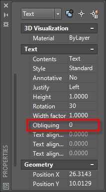
Now select text on the face of dimension C then right click and select Properties from the contextual menu. From the Text panel of properties palette change value of Obliquing to 30.
Repeat the process for text on cube facing dimension B but in this case change obliquing value to -30. The final drawing with isometric dimension and text will look like the image shown below.

Do you have any questions related to isometric text and dimensions? Let me know in comments below.
HOW TO CONTINUE AS PER ISOMETRIC DIMENTION IF IT IS DOING ONE BY ONE ITS TAKEING LONG TIME.
Yo estoy perplejo viendo este tutorial, lo que Ud ha dibujado es erroneo, los textos de las dimensiones no se encuentran en el mismo plano de las líneas de dimensión a las cuales pertececen los textos.
Los textos deben estar en los mismos planos donde están las líneas de dimensión.
I am perplexed watching this tutorial, what you have drawn is wrong, the dimension texts are not in the same plane as the dimension lines to which the texts belong.
The texts must be in the same planes where the dimension lines are.
This is one of most educative sit i have come across. How can i make my dimension lines parallel with vertical lines of the cub? I need help on this.
THANK YOU VERY MUCH A VERY GOOD AND EXCELLENT VIDEO. THE PITCH AT WHICH IT WAS PRESENTED WAS EXCELLENT ESPECIALLY FOR THE SLOW LISTENER.. IT WAS PRESENTED EXCELLENTLY
Thanks you so much.It’s really helpful
Fantastic!! Can’t thank you enough ☺️
Thanks for the wonderful lecture you’ve explained in simple terms. It’s very clear.
Thank you Sir, guidance was very simple and to the point.
thanks …very helpful
ry helpful
NIce read!!!
Thank you
Hellow Jaiprakash Pandey :) i need help, how to make an dimension of isometric view ? give me an example thanks :)
Thanks for the tip Pandey. All I can say is that it is ridiculous to have to go through all this to set a dimension that the program should have applied automatically. After doing most of my work in Solidworks, this is a completely lame exercise to go through just to add a dimension. In Solidworks you click the range and the dimension matches the current plane automatically. One and done.
You can never compare a parametric software like SolidWorks with a non-parametric one like AutoCAD. They are completely different and works in entirely different ways.
Thanks for The tip Mr. Lewis
Hello. How do I dimension a diameter in isometric
I would like to know how to do it too
The tips given in this blog are quite interesting and informative. These are useful to understand how to make isometric dimension and text in autocad. Thanks for sharing this blog. I hope you will come up with more such informative blogs.
Thanks Pandey for your tutorial …..noticed that the arrowheads are not align with the plane ??
Very clear, very concise; exactly what I needed to get this project started. Thank you for your time and instruction!
Namasthay Jaiprakash, you’re a brilliant instructor then why haven’t you enrolled yourself in the ACI program yet? Don’t you think it is worth?
Actually I’m also looking forward to it and was wondering why a man like you is not.
Thanks for your lovely video!
At the time when I was thinking of ACI programme it was not open (was put temporarily on hold) and now I have other obligations which are simply not allowing me to dedicate time to this. I will, however, try to enroll in ACI programme soon. If you are enrolling in it let me know how it goes for you :)
Buen aporte, gracias¡¡
Welcome Mario
Thank you
Namasthey Jay prakash Pandy.
This is very use full to make isometric drawings.why break isometric dimensions?
regards
Aneefa
KSA
If -30 doesn’t work try 330.
thank you, it is very helpful.
i want to ask something. sometime, if i change the angle to -30, the dimension is not change. i try to change it to 30 and then i must change it again to -90. Do you know the answer for my problem?
Thank you very much I appreciate your instructions!
Thanks, I am glad to know this.
So much thanks for tip i use and so happy feel after use this tip
Welcome
You can make the dimensions look more aligned by entering the DDEDIT, this brings you into the Multitext editor and then by highlighting the dimension text and clicking the arrow that pulls down the formatting options, choosing the Oblique Angle, one can change the angle to 30 or -30 as needed. Be sure to have the dimension text highlighted as it will only effect text that is.
Thanks for the tip Lewis