
An Introduction to AutoCAD Sheet Set
The sheet set is like the old file management system reimagined for digital drawings.
Basically, here we put all the drawings of a project together in a single place so that they can be accessed whenever needed.
In this article, I will show you the step-by-step method of making the sheet set using a simple 2-bedroom villa project.
Download the files used for this project here, the following files are available in the downloaded folder.
A set of model drawings of the project in the model drawing folder, label and callout dynamic blocks and the sheet template as shown in the following image.
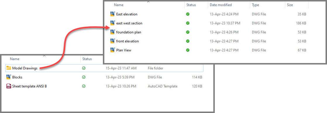
We will be putting all these files together in a meaningful way using the sheet set.
If you prefer video then watch the following video and if you prefer the text tutorial then read on.
Creating the sheet set
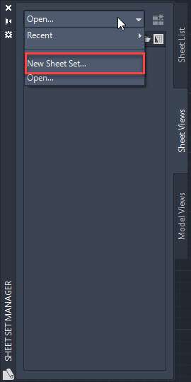
Open a blank drawing using any template and then type SSM on the command line and press enter.
This will open the sheet set manager palette.
Click the Open option on the top of the sheet set manager palette and select the “New sheet set” option from the drop-down as shown in the following image.
Now the Sheet set manager Wizard will open up.
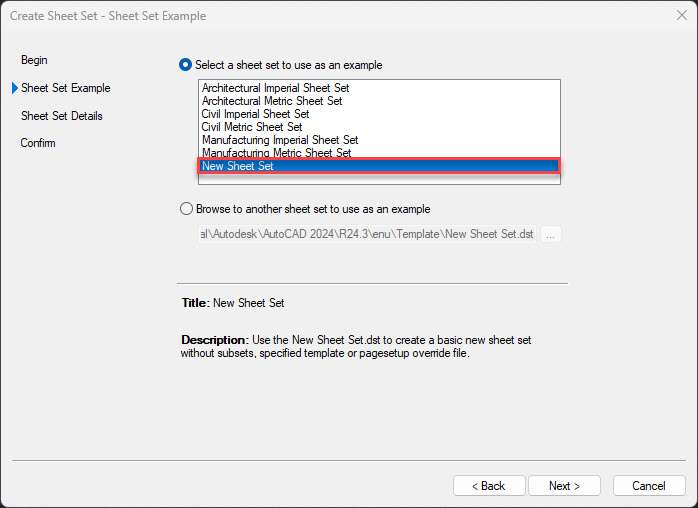
Select “An example sheet set” from the available options and then click on the Next button.
On the next page of the wizard select “New Sheet Set” from the available templates as shown in the following image and click on Next again.
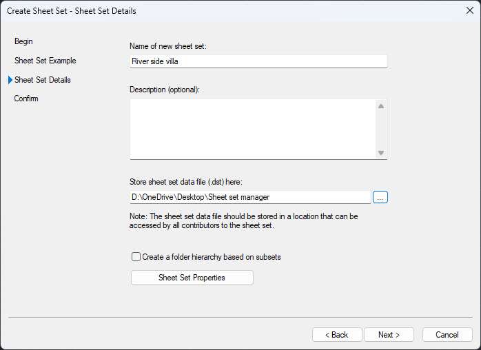
On the next page add the name of the sheet set in the provided space.
I am naming it “River side villa” and then add a description as well, I am leaving the description blank.
In the “Store sheet set data file…” area select the location where you want to save the sheet set file.
I am selecting the same folder “Sheet set manager” where I have all the sheet files on my desktop.
After making all these settings the page should look like the following image.
Now click on the “Sheet Set Properties” button at the bottom of this wizard page.
This will open the Properties palette where we will assign different objects on the sheet set.
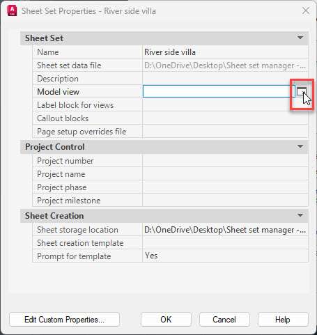
You will notice that the Name and sheet set file location is already set in the palette, we will add the remaining objects to this list.
Click on the Model view empty column and then a small box with an arrow will show up as shown in the following image.
Click that box and then click the Add button in the next palette and select the Model Drawings folder from the sheet set manager folder and then click the Open button.
Click OK again on the next palette to return back to the sheet set manager palette.

Click the empty column next to “Label block for views” and then click the box with an arrow just like in the previous step.
On the next palette click the small box with three dots and then select the “Blocks” drawing from the “Sheet set manager” folder and click open.
In the Select block, palette click the radio button that says “Choose blocks in the drawing file” and then select the “Label block” from the available list as shown in the following image.
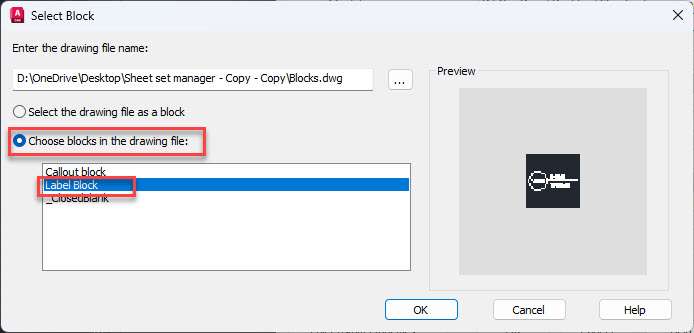
Click OK to close the “Select Block” palette.
Click the blank column next to Callout blocks and then click the box with the arrow and repeat the same steps as above.
The only difference this time is that instead of selecting the Label block select the Callout block from the list of blocks in the “Select Block” palette.
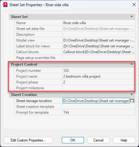
In the next step move to the Project control panel of the “Sheet set properties” palette and then click the empty column next to the Project number and add a number.
I am using 123 as the project number for my example.
In the next field add the project name, I am using “2 bedroom villa project” as the name.
In the project phase, I am using 2 and I will leave the project milestone column empty.
So, after making these changes the Sheet set Properties palette will look like the following image.
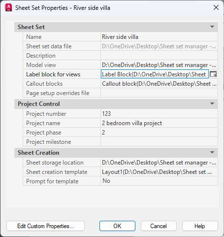
Now let’s go to the “Sheet Creation” panel and here make sure the sheet storage location is the “sheet set manager” folder on the desktop where we saved the original sheet set file.
In the “sheet creation template” select “Sheet template ANSI B” which we have in the “Sheet set manager” folder.
In the last column “prompt for template” select NO as we don’t want AutoCAD to prompt us for a template every time it opens a new sheet in the sheet set manager.
With all these settings the final sheet set properties palette will look like the following image.
Click OK on the Sheet set properties palette and then click Next on the “Create Sheet Set” wizard then click Finish to close the wizard.
Now we have a sheet set called “River side villa” on the Sheet Set Manager palette.
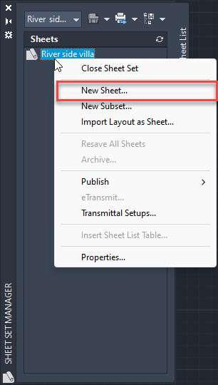
Go to the “Sheet List” tab on the palette and then right-click on the “River side villa” sheet and then select “new sheet…” as shown in the following image.
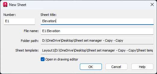
In the “New sheet” palette add a number for the sheet.
I will type E1 for the sheet number and in the Sheet title I will use “Elevation” as the name.
Leave the “File name” field with the default value and click the Open in drawing editor check box as shown in the following image and then click OK.
A new “E1 – Elevation” sheet is now created.
Repeat the same process and create two more sheets with “D1 – Detail” and “P1 – Plan” names.
Now we have three sheets in the “Sheet set manager” palette, let’s add some drawing views in these sheets.
Adding Drawing views
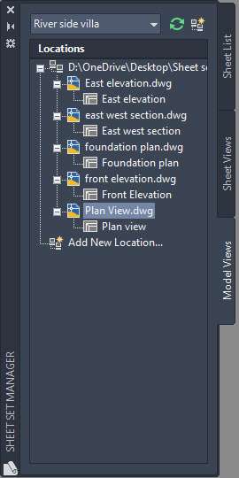
To add the drawing views, go to the Model Views tab of the sheet set manager palette and then expand the file tree by clicking the + icon to reveal all the drawing files and views as shown in the following image.
Open the E1 – Elevations sheet by double-clicking it from the Sheet List tab of the Sheet Set Manager palette.
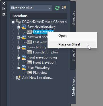
Now Go to the Model Views tab of the sheet set manager palette then right-click on the east elevation view from the list and select “place on sheet” option as shown in the following image.
A really big view of the East Elevation will show up next to your cursor.
Right-click and a scale menu will appear, select 1/8”=1’ from the scale list and then place the view on the top left corner of the sheet making sure it is within the title block boundary.
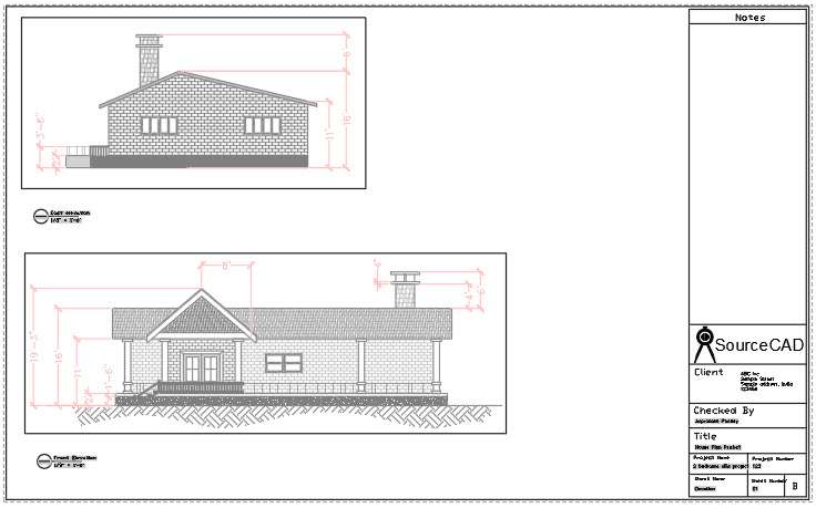
Repeat the process to add the Front Elevation view as well in the same sheet using the same scale at the bottom left corner of the sheet.
After adding both the views the sheet should look like the following image.
Open D1 – Detail sheet by double-clicking it from the “Sheet List” tab of the sheet set manager palette.
Now go to the East-west section view from the “Model Views” tab of the Sheet Set Manager palette and then right click on it and select the “Place on sheet” option then select a scale of 1/8”=1’ just like we did in the previous example and then place it on the top left corner of the sheet.
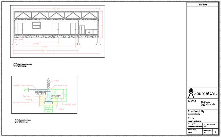
Repeat this process for the “Foundation plan” view but this time use a scale of ¼”=1’ and place it on the bottom left corner of the sheet.
So, after placing both sheets the drawing should look like the following image.
Finally, open the P1 – Plan sheet from the Sheet List tab of the Sheet Set Manager palette.
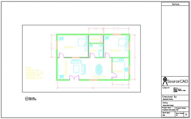
Now place the Plan view from the “Model Views” tab of the Sheet Set Manager palette on the sheet with a scale of 1/8”=1’ exactly at the centre of the sheet.
After adding it the sheet should look like the following image.
Now let’s look at the E1 – Elevation sheet.
You will notice that the title block of this sheet has all the relevant information auto-filled in it and it is using the same information that we used for creating our sheets.
When you look at the label block you will also find that the information like view name and view scale is also auto-filled in it.
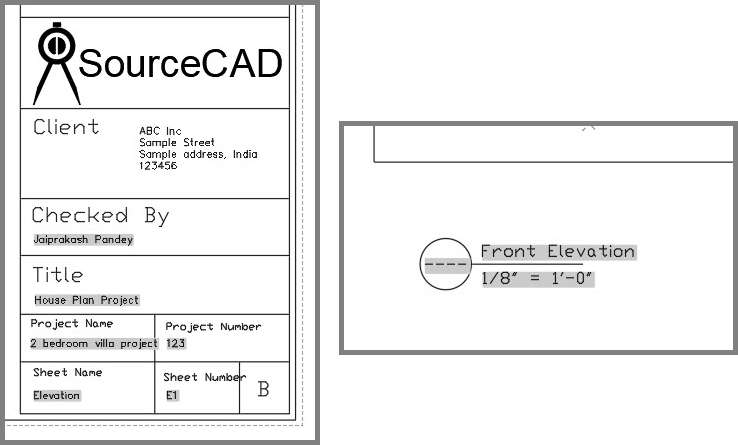
So, that’s the advantage of using this type of sheet set, all of these fields are dynamic information which will automatically change when you change any of these linked properties like scale or sheet name etc and it will be auto-filled.
The only information missing from these sheets is the “view number” in the label block callout.
Let’s add that to our sheets.
To do that go to the “Sheet Views” tab of the Sheet set manager palette and expand all the sheets using the + icon.
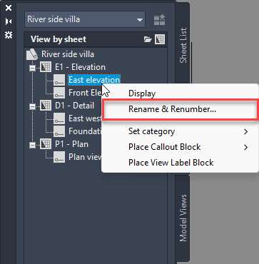
Now right-click on the East elevation view and then select the “Rename & Renumber” option as shown in the following image.
Select 1 as the number for the East elevation view and then click the next button and then select 2 as the number for the Front elevation view.
Click OK to close the dialogue box and then type RE to regenerate the E1 – Elevation sheet and the numbers will now show up in the label block of the sheet.
Repeat the same process of numbering the views for D1 – Detail and P1 – Plan sheets and now we have view numbers for all the sheet views.
Adding Callout blocks
Now that we have the label blocks in the drawing let’s add the callout blocks and for that open the “P1- Plan” sheet from the sheet list tab of the Sheet Set Manager palette.
In the plan view select the rectangular viewport boundary and then put it on the VP layer.
This VP layer was created for the viewports in the template.
After putting it on the VP layer freeze the layer so that the boundary disappears.
You can hide the viewport boundaries using a similar method on other sheets as well.
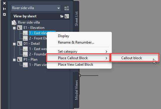
Now go to the “Sheet Views” tab of the Sheet Set Manager palette and right-click on the East Elevation view and select the “Place callout block” and then “Callout block” from the list as shown in the following image.
Place the callout block on the East side of the plan view.
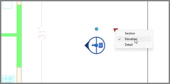
Click the block and change it to Elevation from the Visibility grip and then using a rotate grip that looks like a blue circular dot, rotate it to face the east side of the plan as shown in the following image.
Repeat the same steps again for the Front elevation and place the callout at the front of the plan view.
Now go to the east-west section view and then add the section callout on the west side of the plan view and add a section line as well passing through the Drawing Room and Kitchen as shown in the following image.
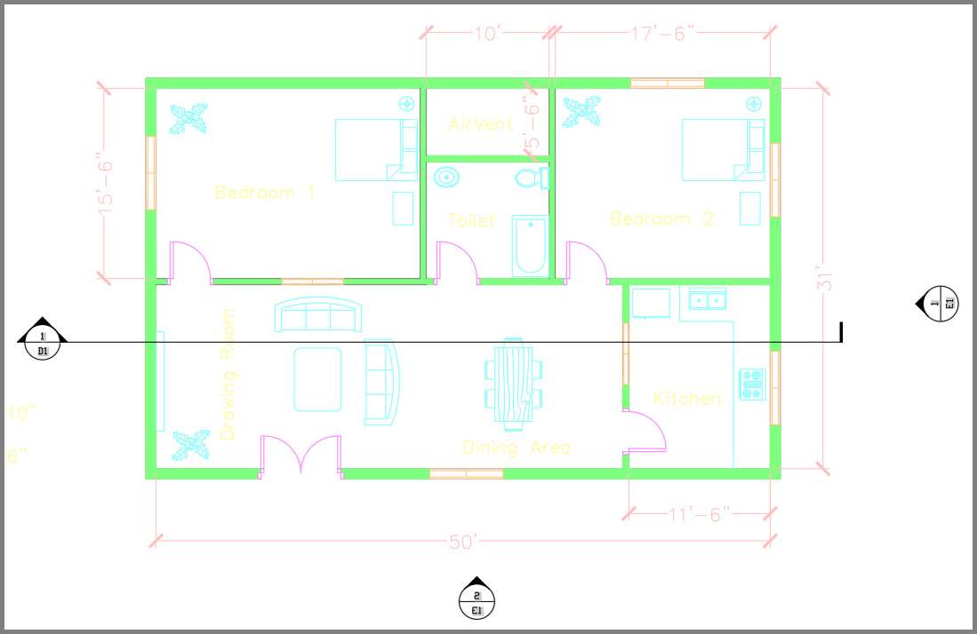
In a similar way, you can add callouts linking different parts of the views in any sheet.
Publishing and eTransmitting the sheet set
After the sheet set is fully prepared you can publish it as a single PDF file or as a DWF file.
For this example, we will publish the sheet set as PDF.
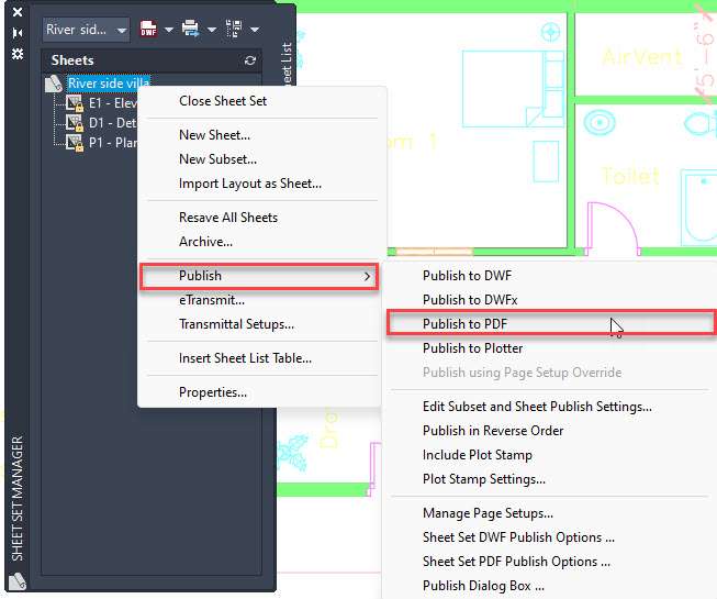
Go to the Sheet list tab and then right-click on the River side villa sheet name and then select “Publish” and then the “Publish to PDF” option as shown in the following image.
Now specify a location where you want to save this PDF file and then click the “Select” button and the sheet set will be published as a single PDF file.
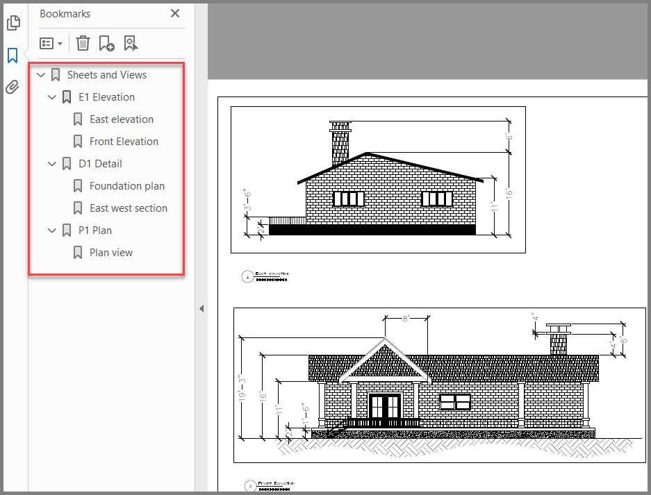
In this PDF you can go to the bookmarks and navigate to different Sheets and even views as shown in the following image.
If, however, you want to send this entire sheet set along with all the related files then you need to use the eTransmit option of AutoCAD.
eTransmit will create a ZIP package of all the model drawings, sheets, DST files and everything else that is used in the project and then you can share this ZIP package with anyone.
To create the eTrasmit once again right click on the “River side villa” sheet on the sheet set manager palette and select the eTransmit option from the context menu.
Before you do that make sure all your sheets are saved or else eTransmit will not work.
In the Create Transmittal palette click OK and now we have a ZIP package containing all the sheet set files.
Conclusion
The sheet set is a big topic and the simple sheet set that we created here is just the tip of the iceberg.
There is quite a lot you can do with Sheet sets and if you want to explore in-depth about sheet sets then check the AutoCAD sheet set course.
Are you planning to now use the sheet set in your projects? Let me know in the comments below.
Now I am using 2014 autocad I forget autocad short keys. If you have please send me
This is a great introduction to CAD and I am sure it will be very useful for many who are learning the ropes
Thanks Gervase.
hey i have project assembly drawing in my faculty can you help me in plotting it and how to make it