Author: Jaiprakash Pandey

  • An introduction to Parametric Drawing, Constraints and Formulas in AutoCAD

    An introduction to Parametric Drawing, Constraints and Formulas in AutoCAD

    The parametric drawing is a method of making geometries with geometrical or dimensional constraints or restrictions. These constraints are applied to the geometry with respect to certain references or other geometries. Parametric drawings update itself if any one parameter is changed, this also helps in maintaining design intent.

    This feature of parametric drawing was introduced in 2010 version of AutoCAD. This article explains the concepts of Parametric Drawing, Constraints and Formulas in AutoCAD. Let’s start with applying constraints in the drawing with the help of a simple drawing.

    Applying Constraints:

    Make a rectangle with any dimensions and a circle at the geometric center of the rectangle. Now go to the Parametric tab and select the linear option from the Dimensional panel. Click at the top left vertex of the rectangle and then click at the top right vertex and place the linear constraint. Similarly, apply the linear constraint on any one vertical side of the rectangle.

    5
    Linear constraint on Dimensional panel

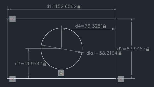
    The dimensional constraint is different from the simple dimensioning and should not be confused with that. Select Diameter constraint from Dimensional panel and apply it to the circle at the geometric center of the rectangle. Now apply the linear constraint to the circle with respect to the horizontal and verticle side of the rectangle.

    Now select Fix constraint from the Geometric panel and click at two diagonally opposite vertices of the rectangle to make it fixed. Now select Perpendicular constraint and apply it on three vertices of the rectangle. The geometry is now fully constrained as shown in the image below.
    Making simple formulas:

    Let’s assume that we want the geometry made above to behave in such a way that diameter of the circle always remains half of length of the rectangle. For that, we can create a simple relation or formula and apply it to the respective geometries in the drawing.

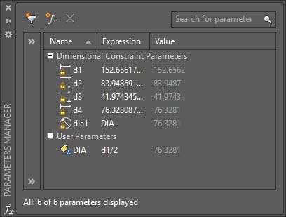
    Click on Parameters Manager icon on Manage panel of Parameters tab or use its command equivalent PARAMETERS. Click on the 2016-09-05_19-41-46 icon on Parameters Manager palette, a new list User Parameters will be added to the palette.
    Parametric Drawing, Constraints and Formulas in AutoCAD
    Parameters manager palette

    Double click on the user1 parameter and change its name to DIA. Double click again on expression column next to DIA and type d1/2 which mean DIA parameter will be equal to d1/2 where d1 is the length of the Rectangle.

    You can now use this formula to define the diameter of the circle, double click on Expression column of dia1 row in parameters manager palette and change it to DIA as shown in the image above, the circle will update according to changed dimension and diameter of circle will become equal to value of DIA which is half of length of rectangle.
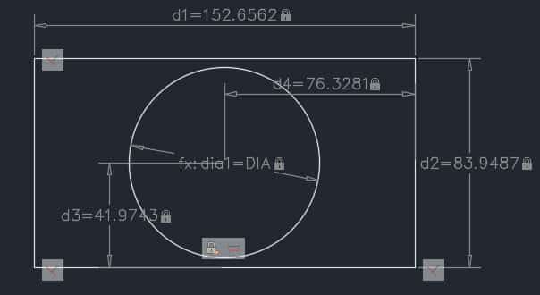
    To test this formula go to d1 in drawing area and change its value, you will notice that diameter of the circle will also change accordingly not only in parameters manager palette but also in the drawing area.

    Making nested formulas:

    In the above example, I have used a simple formula but you can also use nested and complex formulas that involve the use of sine, cosine and logarithmic expressions. I will use the same example of rectangle and circle to explain this as well.

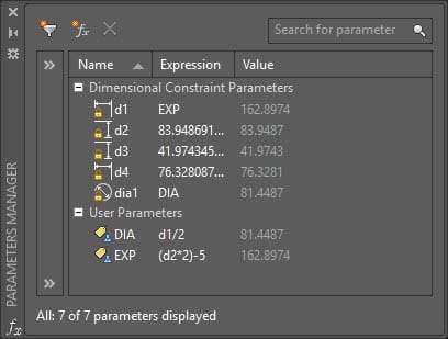
    Suppose we want to change the length of the rectangle (d1) in such a way that it always remains five units less than twice of the width of the Rectangle (d2) then we can use this expression (d2*2)-5 to define the length of the rectangle where d2 is the width of the Rectangle.

    To apply this formula click on the  icon and double click on user2 and rename it to EXP. Again double click on the expression box next to EXP and write the expression (d2*2)-5.

    Now write EXP in d1 row expression column as shown in the image below. You will notice that length of rectangle changes to reflect dimension according to formula. Final settings in parameters manager will look like this.
    Parametric Drawing, Constraints and Formulas in AutoCAD
    The final parameters in Parameters manager palette

    You can test this nested expression by changing the value of d2 which will change dimensions of all dependent geometries including the diameter of the circle.

    Do you have questions related to this tip? Let me know in comments below.

  • Restore the classic Workspace in AutoCAD 2016 and 2017

    Restore the classic Workspace in AutoCAD 2016 and 2017

    [fusion_builder_container hundred_percent=”no” equal_height_columns=”no” menu_anchor=”” hide_on_mobile=”small-visibility,medium-visibility,large-visibility” class=”” id=”” background_color=”” background_image=”” background_position=”center center” background_repeat=”no-repeat” fade=”no” background_parallax=”none” parallax_speed=”0.3″ video_mp4=”” video_webm=”” video_ogv=”” video_url=”” video_aspect_ratio=”16:9″ video_loop=”yes” video_mute=”yes” overlay_color=”” video_preview_image=”” border_size=”” border_color=”” border_style=”solid” padding_top=”” padding_bottom=”” padding_left=”” padding_right=”” admin_toggled=”no”][fusion_builder_row][fusion_builder_column type=”1_1″ layout=”1_1″ background_position=”left top” background_color=”” border_size=”” border_color=”” border_style=”solid” border_position=”all” spacing=”yes” background_image=”” background_repeat=”no-repeat” padding_top=”” padding_right=”” padding_bottom=”” padding_left=”” margin_top=”0px” margin_bottom=”0px” class=”” id=”” animation_type=”” animation_speed=”0.3″ animation_direction=”left” hide_on_mobile=”small-visibility,medium-visibility,large-visibility” center_content=”no” last=”no” min_height=”” hover_type=”none” link=””][fusion_text]

    Autodesk has abandoned its old classic workspace from AutoCAD 2015 and later versions but you can easily bring it back to its full glory with a few tweaks to your new AutoCAD software. You can restore the classic workspace in AutoCAD 2016 and 2017 versions (including 2015 version) using the tips mentioned in the article.

    Although I will also recommend you to embrace this change and move on with the new workspace but if you are still not comfortable enough with the change then read on to find the ways of restoring classic workspace.

    I have also prepared this video which explains this tip in detail, but if you prefer you can read the article instead by scrolling down.

    [/fusion_text][fusion_youtube id=”IEJmx9YngBI” alignment=”center” width=”” height=”” autoplay=”false” api_params=”” hide_on_mobile=”small-visibility,medium-visibility,large-visibility” class=”” /][fusion_text columns=”” column_min_width=”” column_spacing=”” rule_style=”default” rule_size=”” rule_color=”” hide_on_mobile=”small-visibility,medium-visibility,large-visibility” class=”” id=”” animation_type=”” animation_direction=”left” animation_speed=”0.3″ animation_offset=””]

    Import from the previous version:

    Open AutoCAD 2014 or any previous version which has classic workspace and change workspace to Drafting and Annotation. Now type CUI on the command line to bring Customize User Interface window, from this window go to transfer tab and select Save As from Main customization file (acad.cuix) drop-down menu as shown in the image below.

    Specify a location where you want to save this file and give it a name, I am naming it as My workspace and click OK. If you don’t have any previous version of AutoCAD then you can use cuix file I created, download it here.

    Restore the classic workspace in AutoCAD 2016 and 2017

    Now go to AutoCAD 2015 or 2016 and type CUI again to bring Customize user interface window. Go to transfer tab and click on the open button from Customizations in new file panel as shown in the image below. Locate the cuix file saved in steps above and open it.

    You will find all workspaces including AutoCAD classic in the workspaces tree on right. Drag and drop AutoCAD classic workspace from right panel to left in the workspaces tree, refer image below. Click on OK to save the settings and exit CUI window.

    Restore the classic workspace in AutoCAD 2016 and 2017

    Now, when you click on workspace switching you will see classic workspace in it and you can seamlessly toggle between classic and other workspaces.

    Migrating Custom Settings:

    Restore the classic workspace in AutoCAD 2016 and 2017

    You can also migrate custom settings of AutoCAD directly using it’s Migrate Custom Settings option from the start menu. This migrates AutoCAD classic along with other workspaces of the previous version.

    Click on Migrate From a Previous Release option from the start menu as shown in the image above and check user profiles radio button. You can keep other buttons checked if you want to migrate those settings also.

    Make sure that previous version of AutoCAD containing classic workspace is selected in the drop-down menu. In the image above AutoCAD 2013 is selected in the drop-down menu. Also make sure that previous release of AutoCAD is installed from which you want to migrate settings, look at the image above for reference.

    Restore the classic workspace in AutoCAD 2016 and 2017

    Now open new AutoCAD version and type CUI on the command line and press enter. Customize user interface window will pop up, select customize tab in CUI window if it is not already selected. You will see that four new workspaces will be listed there as shown in the image above.

    Now delete all migrated workspaces except AutoCAD classic by right-clicking on workspaces and selecting delete option from the contextual menu. You can also rename migrated AutoCAD classic workspace to a shorter name by selecting Rename from the contextual menu.

    Once you have made all these changes click on OK button to close the window, now you will see AutoCAD classic listed in workspace drop-down menu.

    Do you have questions related to this tip? Let me know in comments below.

    [/fusion_text][/fusion_builder_column][/fusion_builder_row][/fusion_builder_container]

  • How to find number of objects in AutoCAD drawing

    How to find number of objects in AutoCAD drawing

    [fusion_builder_container hundred_percent=”no” equal_height_columns=”no” menu_anchor=”” hide_on_mobile=”small-visibility,medium-visibility,large-visibility” class=”” id=”” background_color=”” background_image=”” background_position=”center center” background_repeat=”no-repeat” fade=”no” background_parallax=”none” parallax_speed=”0.3″ video_mp4=”” video_webm=”” video_ogv=”” video_url=”” video_aspect_ratio=”16:9″ video_loop=”yes” video_mute=”yes” overlay_color=”” video_preview_image=”” border_size=”” border_color=”” border_style=”solid” padding_top=”” padding_bottom=”” padding_left=”” padding_right=”” admin_toggled=”no”][fusion_builder_row][fusion_builder_column type=”1_1″ layout=”1_1″ background_position=”left top” background_color=”” border_size=”” border_color=”” border_style=”solid” border_position=”all” spacing=”yes” background_image=”” background_repeat=”no-repeat” padding_top=”” padding_right=”” padding_bottom=”” padding_left=”” margin_top=”0px” margin_bottom=”0px” class=”” id=”” animation_type=”” animation_speed=”0.3″ animation_direction=”left” hide_on_mobile=”small-visibility,medium-visibility,large-visibility” center_content=”no” last=”no” min_height=”” hover_type=”none” link=””][fusion_text columns=”” column_min_width=”” column_spacing=”” rule_style=”default” rule_size=”” rule_color=”” hide_on_mobile=”small-visibility,medium-visibility,large-visibility” class=”” id=”” animation_type=”” animation_direction=”left” animation_speed=”0.3″ animation_offset=””]

    In AutoCAD, there is no direct command for finding the number of entities with a particular property but you can harness features of quick select tool to do this task. I will illustrate this tool with the help of two simple examples.

    Finding the number of circles of particular radius:

    Let’s assume that we want to know the number of circles with radius 2 units from our drawing. To do that click on the Quick select tool on the Utilities panel of Home tab. Alternatively, you can also use its command equivalent QSELECT.

    Find number of objects in AutoCAD

    From Apply to drop-down menu of the Quick Select window select Entire drawing option. In next menu, a list of all items present in the drawing will appear select circle from object type drop-down menu.

    Now all the properties associated with circle will be listed in the properties panel, select the radius from the Properties panel.

    Select =Equals operator from next menu and enter the radius of the circle in the Value field. In this case, I am entering 2 as the radius then click OK. If you want to select all circles in the drawing with the radius greater than 2 units then select > greater then operator, similarly other operators can be chosen depending upon your requirement.

    Once you have made all settings in Quick select window click OK. You will see the number of circles with radius 2 units above command line as shown below.

    If you want to find the total number of circles in the drawing then select radius in property menu. From the Operator menu, select the Greater than operator and enter 0 in the value field. It’s obvious that radius of all circles present in the drawing will certainly have a value greater than zero!

    In a similar way, you can create as many criteria as you want for finding or selecting objects of a particular property from your drawing. Quick select will not include objects which are present in a block even if they meet the criteria described by the quick select command.

    To find the number of Blocks in a drawing:

    AutoCAD offers a direct command BCOUNT for finding the number of each block used in the drawing. This command can only count active blocks in your drawing which means if you have a block which is not used in the drawing area then the result will not contain its count.

    To see the number of blocks type BCOUNT on the command line and press enter then select an area in the drawing from where you want to count blocks. To count the number of blocks in entire drawing don’t select an area directly press enter and the complete drawing will be selected.

    Find number of objects in AutoCAD

    Once you have made selection press enter to get results, the final count of blocks will appear above the command line as shown in the image above.

    You can expand command line to see the result or type F2 to bring a popup window with command history containing results.

    Do you have questions related to this tip? Let me know in comments below.

    [/fusion_text][/fusion_builder_column][/fusion_builder_row][/fusion_builder_container]

  • Divide AutoCAD objects into equal parts – Review

    Divide AutoCAD objects into equal parts – Review

    [fusion_builder_container hundred_percent=”no” equal_height_columns=”no” menu_anchor=”” hide_on_mobile=”small-visibility,medium-visibility,large-visibility” class=”” id=”” background_color=”” background_image=”” background_position=”center center” background_repeat=”no-repeat” fade=”no” background_parallax=”none” parallax_speed=”0.3″ video_mp4=”” video_webm=”” video_ogv=”” video_url=”” video_aspect_ratio=”16:9″ video_loop=”yes” video_mute=”yes” overlay_color=”” video_preview_image=”” border_size=”” border_color=”” border_style=”solid” padding_top=”” padding_bottom=”” padding_left=”” padding_right=”” admin_toggled=”yes”][fusion_builder_row][fusion_builder_column type=”1_1″ layout=”1_1″ background_position=”left top” background_color=”” border_size=”” border_color=”” border_style=”solid” border_position=”all” spacing=”yes” background_image=”” background_repeat=”no-repeat” padding_top=”” padding_right=”” padding_bottom=”” padding_left=”” margin_top=”0px” margin_bottom=”0px” class=”” id=”” animation_type=”” animation_speed=”0.3″ animation_direction=”left” hide_on_mobile=”small-visibility,medium-visibility,large-visibility” center_content=”no” last=”no” min_height=”” hover_type=”none” link=””][fusion_text columns=”” column_min_width=”” column_spacing=”” rule_style=”default” rule_size=”” rule_color=”” class=”” id=””]

    Using DIVIDE and MEASURE commands of AutoCAD you can divide 2D drawing objects like Line, Polyline, Arc, Spline and Ellipse in equal parts without knowing their length.

    These commands will not split the geometry instead at every division a point will be added. The commands can be used on open geometries like an arc and also on closed geometries like a circle.

    DIVIDE command:

    In order to divide the geometry into a fixed number of divisions use DIVIDE command. For our case, I will use a spline.

    Select Divide tool from expanded Draw panel of Home tab, you can also use its command equivalent DIVIDE. Click on the spline and enter the number of segments in which you want to divide the spline, I will select 6 segments for our case. Press enter to exit the command.

    DIVIDE autocad object

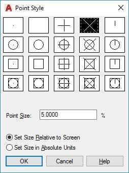
     You will see no visible changes on the spline, to see the changes type DDPTYPE and press enter. This will open Point Style window, select a visible point style from this window and click on OK.

    DIVIDE autocad object

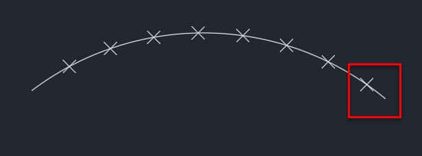
    You will now see points on the spline that divide the entire geometry into six equal segments.

    Blocks for Division:

    You can also use blocks instead of points at the division points of the geometry. In order to use the blocks start DIVIDE command select the object and click on Block from options of the command line as shown in the image below.

    divide with blocks autocad

    Type name of Block and press enter again. If you want to align the object with respect to the geometry select yes from the next prompt else select no. Specify the number of segments in which you want to divide the geometry and press enter.

    You will notice that an instance of selected block will be added at the point of division of the geometry.

    MEASURE command:

    MEASURE command can be used in the situations where you want to divide the object into segments of known length.

    For example, if we have an arc and we want the arc to divide in such a way that each segment is equal to 3.6 units then this command can be used.

    However, there is a limitation with this command when you use this command on any geometry the length of the last segment may or may not be equal to the length assigned by you.

    The last segment length depends entirely on the remaining length of the curve after performing the divisions as shown in the image below.

    DIVIDE autocad object

    For example, if you use measure command to divide a line of length 9 units in a segment length of 2 units then the line will be divided into four equal parts of 2 unit length but the last segment will be 1 unit in length.

    To use this command select MEASURE tool from expanded draw panel of Home tab, you can also use its command equivalent MEASURE.

    DIVIDE autocad object
    Select the geometry and type the length of segment and press enter. You will notice that a node will be added at each division points similar to DIVIDE command. In this case, as well you can use blocks instead of points.

    Do you have questions related to this tip? Let me know in the comments below.

    [/fusion_text][/fusion_builder_column][/fusion_builder_row][/fusion_builder_container]