In AutoCAD renderings, many objects like vehicles and trees can be added to give it a more realistic appearance using a material created with opacity maps. To make these objects we need to create a material with image and it’s equivalent opacity map which if rendered in a 3D drawing will create the illusion of a realistic 3D object in the drawing.
Opacity map is a greyscale image in which black part is completely transparent and white is opaque and different levels of gray in the image decides the amount of transparency of the image.
In this article, I will explain the method of making a 3D realistic tree for our rendering.
I have prepared this video explaining all the steps mentioned in this article but if you don’t prefer the video then scroll down for the article.
For our example, I am using the image of the tree and it’s opacity map as shown in the image below. You can easily create opacity map from an image using photo editor tools like Photoshop. You can download the tree image with its opacity map and sample drawing used in this article from this link.
Open Rendering DRG drawing file and switch to AutoCAD 3D modeling workspace. Go to Visualize tab and click on Materials Browser icon to open it alternatively, you can also use its command equivalent MAT.
Click on the New material button on the lower left corner of materials browser palette as shown in the image below and select New Generic Material from the menu.
A new Materials Editor palette will pop up, enter the name of this new material, I am naming it as New Tree. From this palette expand the Generic group and double click on the box next to the image option.
Locate the tree image and click on Open. Double click on the image again to open the Texture Editor palette. Expand the scale group from the Texture Editor palette and change sample size in width and height to 12 units.
Expand Repeat group as well in the texture editor palette and select None from Horizontal as well as Vertical drop-down menu. Once you have made all of these changes close Texture Editor palette.
Scale and Repeat group in texture editor
Again go to Materials Editor palette and click on the Cutouts group, a new file browser will appear. Locate tree opacity map image and click Open to load it in the material.
Now double click on the image in the Cutouts group and change its scale to 12 units in Width and Height fields and also from Repeat group change Horizontal and Vertical values to None.
Applying Tree material to drawing
After making all of these changes close all open palettes except Materials Browser. Make a surface in drawing with length and height equal to 12 units.
Drag and drop New Tree material on the surface created in the previous step and your material will be applied to it. Change the visual style to Realistic from Visual Styles panel of Visualize tab.
Your drawing is now ready for rendering, click the Render to Size icon on the Render panel of Visualize tab and wait for the rendering to complete. The rendering which I obtained with settings mentioned in this article is shown below. I have used a background in the drawing to make the tree and its shadow more prominent.
Do you have questions related to this tip? Let me know in the comments below.
The annotative property was added in the AutoCAD 2008 version and it is a useful tool for keeping annotation size constant in AutoCAD. Prior to the induction of the annotation scale of AutoCAD, the task of plotting objects with the correct scale for different viewports was a tedious job.
One had to make multiple copies of the same object for different scales and the objects were then put on different layers and for each viewport or scale of drawing only appropriate layer was turned on keeping rest of the layers off.
This process results in an unnecessary amount of data in drawing leading to confusion and larger file size and it’s needless to say that it also causes wastage of drafting time. The annotative property took this trouble out of drawing process.
Understanding Annotative property:
Let’s assume that we have a floor plan with maximum exterior dimensions of 525 inches and 336 inches. Now in order to plot this drawing on a normal A3 size sheet of paper which is 420 X 297 mm we need to decrease the overall scale of drawing to appropriate size.
Let’s select a scale of ¼” = 1’ which in layman’s term can be summed up as 0.25 inches on paper equals 1 feet on actual drawing. Now with this scale, the drawing looks like this on A3 paper.
Here all dimensions, text and blocks are clearly visible with respect to the viewport. Now here is another drawing in which only the kitchen is included at a zoomed scale of 1” = 1’
Now obviously with a change of scale of viewport the scale of dimension text also changed in same proportion which you can see in the drawing but do we really need large dimension text as seen in figure 2?
Obviously, we don’t need large text we want uniform text and dimension size throughout different scales of the drawing. So we can assign the annotative property to dimension and text and keep its size fixed in different scales throughout the drawing.
Figure 3 is again plotted at the scale of 1”=1’ but with annotative property assigned to the dimension text in which size of dimension text is equal to its size in A3 sheet (figure 1) where the scale was ¼”=1’ making it look more consistent.
Making Annotative dimension:
To make annotative dimension style type DIMSTYLE on the command line and press enter. A new dimension style manager window will pop up, click on the new button on right side of this window. Now give your dimension style a name, I am naming it as “My Anno Dim” and check the annotative radio button then click on continue.
Figure 4
New dimension style window will pop up with multiple tabs, select text tab and change the size of text to 1/8” or whatever paper height of text you want to keep in all scales. Similarly, change arrow size from symbols and arrow tab to 1/8”.
If you already have a dimension style for your drawing and you want to make that style annotative then select your dimension style from dimension style manager then go to fit tab and check the annotative radio button from the scale for dimension features panel.
Click on OK to close new dimension style manager and then click on close from dimension style manager window too.
Figure 5
Now our drawing is prepared with a new annotative dimension. Make My Anno Dim dimension style current by selecting it from dimension style drop down and add dimensions to the drawing in model space using current annotative dimension style.
Adding Scale to Annotative dimensions:
Before preparing the layout for final plotting we should decide the scales in which we want to plot our drawing. Let’s assume that we want to plot the drawing on A3 paper size and on three different scales 1”=1’, 1/8”=1’ and ½”=1’.
In order to make annotative dimensions visible on all of these scales, we need to add these scales to the dimensions. From status bar click on add scales… button to turn it on, you can also turn on show annotation objects button to see a real-time effect of the change in scale on your drawing, see figure 6 for reference.
Figure 6
For adding scale in an older version of AutoCAD type OBJECTSCALE on the command line and press enter then select all dimensions for which you want to add scales then press enter again. Annotation object scale window will pop up, select add button and add scales to the list and click OK to close all open windows.
Figure 7
Now click on scale drop down menu next to add scales button and select scale 1”=1’ from the drop down menu, repeat the process for 1/8”=1’ and ½”=1’ scales also. Now the scales are added to the drawing and our drawing can now be prepared for plotting.
Do not add many scales to the annotative dimensions because it may cause a lot of background processes and as a result, your software performance may suffer.
Preparing layout views:
Go to layout tab and type PAGESETUP on the command line and press enter, select modify from page setup manager window and select ISO A3 paper size from the Paper Size drop-down menu of page setup window. Click OK to close page setup window.
Now create three rectangular viewports in paper space and assign scales of 1”=1’, 1/8”=1’ and ½”=1’ to three viewports. You will notice that although we have different drawing components like text, blocks and geometries on different scales but the size of dimension text is constant throughout the viewports because of annotative property assigned to them.
If you change the scale of any of these viewports to the value other than the one which is assigned to annotative dimension then the dimensions will not appear for that scale. In order to make dimension appear for a new scale, you need to add that scale to the annotative dimensions as explained above.
Changing visibility of annotative object:
You can change the position of your annotative object according to the scale. For example, in the scale of 1”=1’ the dimension appears in the middle of the dining table but for a scale of ½”=1’ the dimension may be made to appear outside dining table for the same dimension as shown in figure 8.
Figure 8
To change the visibility of these objects simply activate viewports by double-clicking within them and move dimensions using grips to the position where you want it to appear for the particular viewport, the position of the annotative object will not change in another viewport.
Conclusion:
The methods explained in this article can be used for assigning annotative scales to other objects like Blocks, Hatch and Mtext also. The annotative feature is a great time saving and productivity tool that should be used in the drawing wherever required.
This tool not only helps in making a more organized and professional drawing but it also helps in keeping useless clutter out of the drawing that you are forced to use if not using annotative property.
Do you have questions related to this tip? Let me know in comments below.
Autodesk has released its new AutoCAD 2017 version and there are some exciting enhancements in this release. In this article I have listed six new features of AutoCAD 2017 version that I found appealing at first look, I will add more features to this list soon.
To see system requirements for AutoCAD 2017 see this page on Autodesk knowledge network.
Autodesk Desktop app:
The new Autodesk desktop app is added in the latest release of AutoCAD where you can manage software updates, watch latest videos and articles for learning software skills, access forums and Autodesk knowledge network. You can also use Autodesk desktop app for sending feedback to Autodesk and accessing online AutoCAD help.
PDF to DWG:
This is probably the most awaited feature in AutoCAD, starting with AutoCAD 2017 you can import drawings from PDF format to AutoCAD as geometry and text objects.
So far there were many third party tools which in my opinion were very buggy and inefficient in doing the so called task of converting PDF to DWG drawings hence the addition of this feature is a great enhancement to AutoCAD features.
To use this feature type PDFIMPORT on the command line and press enter then select the file from command line and locate PDF file from your computer and click on open. Now an Import PDF window will open select all required options from this window and click on OK.
AutoCAD drawing will be imported as text and geometry and you can customize these objects easily.
Sharing drawings:
You can now directly share files with users who don’t even have AutoCAD using A360 cloud account and all they need is a web browser for accessing shared drawing.
To share a drawing make sure you are logged into your Autodesk 360 cloud account and your drawing is saved on local or network drive.
Click on application button on top left of AutoCAD window select Publish then Design Views from options. Select one of the two options from next notification window and wait for the drawing to upload and process for viewing.
Once your drawing is ready for viewing you will get a bubble notification in your AutoCAD window click on it to open the drawing in the web browser. Click on Get Link icon in the top right corner of A360 viewer and copy the link.
You can now share this link with users and end user will not even require AutoCAD software or A360 account for viewing this drawing.
Making centerline and center marks:
With new AutoCAD 2017, you can easily add center lines and center marks to the geometry. Simply type the command CENTERMARK and click on the circular object to create the center mark. You can use this command to make a center mark on circle, arc and fillet.
In order to create a center line between objects such as two parallel or intersecting lines type command CENTERLINE press enter and select both parallel or intersecting lines. A center line will be created in between both the lines.
These center lines and center mark will remain associated with the objects with reference to which they are created. When you change the position of those original objects then the center line and center mark will update its position.
With new Autodesk print studio, you can make a 3D print ready file and directly print it in almost all types of 3D printers. This 3D printing tool is provided by spark technologies and it is available for 64 bit machines only.
To use this tool go to AutoCAD 3D modeling workspace and select print studio tool from 3D print panel of output tab. If you are using this tool for the first time then a prompt will appear from where you can download this tool.
Once downloaded and installed click on print studio tool again and click on watertight or closed mesh object from your drawing which you want to use for 3D printing.
This model will open in new Print studio window where you can prepare this model for 3D printing. If you are not yet ready to print this drawing then you can export it as STL file which can be used later.
Migrate custom settings:
The new custom settings migration setting window is more visually appealing and has easy to understand interface.
Enhanced graphics:
With new AutoCAD, you will see an enhanced graphics in 2D and 3D with improved performance and smooth visible features.
For a more comprehensive list of AutoCAD 2017 enhancements see this article of Autodesk blog.
Which new feature did you like most in AutoCAD 2017? let us know in the comments below.
In AutoCAD this tool offers an efficient method of copying properties of one object to another with complete control over properties copied.
Let’s assume that we have an object with particular set of properties like lineweight, linetype, layer and transparency assigned to it and we want to transfer exact properties of that object to another object in same or different drawing then we can directly use this tool instead of assigning individual properties to the destination object.
How to access this command:
You can start match properties command by using its command equivalent MA. You can also place this command on quick access toolbar for easy access if you use it frequently. To place it on quick access toolbar click on the arrow on far right of the toolbar and select Match properties from drop down menu. The match properties icon will appear on Quick access toolbar.
Transferring properties:
In order to copy properties type MA on the command line and press enter, now your cursor will change into a Pickbox and command line will prompt you to select source object from which properties will be copied. Click on object from drawing area then click on destination object on which you want to transfer those properties. You can select multiple objects for pasting properties as well.
In order to transfer properties between different drawings open both source and destination drawings. Type MA press enter then select object from source drawing to copy properties then go to drawing in which you want to paste properties, you will notice that match properties command is still active in the second drawing. Now click on object(s) on which you want to transfer properties.
Deciding which property to copy:
You can also decide which property to copy using match properties command. For changing settings of match properties command type MA on command line press enter then select any object from your drawing area. You will notice this prompt on command line.
Select Settings from command line, property settings window as shown below will pop up.
From this property settings window mark check boxes for the properties which you want to transfer and uncheck all other check boxes. When you have made your selection click on OK to close this window and continue match properties command.
A similar command “Add Selected”:
With Add selected option you can create an object in drawing like polyline, circle, dimension, Block etc with the properties of an existing object from the drawing.
For example, If you have a dimension in the drawing which is not on current layer and has a particular dimension style then you can directly select this option to create a new dimension copying exactly same properties of layer and dimension style.
To use this tool select an object which you want to make then right click in the drawing area and choose add selected from the contextual menu.
The respective command will activate allowing you to make that object. You will notice that your new drawing object inherits all its properties from its source object.
Do you have questions related to this tip? Let me know in comments below.
I believe that this is one of the most underutilized tools of AutoCAD and most people are not even aware of its existence, even I was unaware of its existence but recently I read about it and decided to share it with you.
Reference manager is like a control panel of all reference files of your drawing, it stores the path of every dependent file like font style, plot style tables, X-ref etc. which are generally accompanied with the drawing.
This tool can help you in identifying all missing files in a drawing and not only that you can even re-associate those missing or broken file paths using this tool.
You can’t open reference manager from your AutoCAD window, to open it go to start button in your windows PC select All Programs option then expand Autodesk folder and select your installed AutoCAD version then select Reference Manager from expanded list. Once reference manager is open you will see a window like the one shown in the image above.
[/fusion_text][fusion_text]
You will notice an error icon in the left pane of this window indicating that no drawing is added to it. Click on Add drawings button on the top left of this window locate your drawing and add it, you will see a prompt asking you to load all reference or first level references. If you want to analyze all nested referenced drawings then select load all references else select only first level references.
You can add DWG, DWT and DWS files to reference manager and you can also add multiple files to the reference manager.
Once your drawing is open you will see a list of all drawing entity type in the left pane and also you will see a list all entities in the right pane with their path, as shown in the image below.
You will notice that a green check mark appears in the status of most of the entities, these are resolved entities but there are also some entities shown with an exclamation mark which AutoCAD was not able to resolve and a “Not Found” button appears in the status of those unresolved entities.
To make sure AutoCAD finds these missing entities you need to repair their broken path. If you know the path of missing entity then double click on the unresolved entity or select it then click on Edit selected paths button on the top of Reference manager window. You can also press and hold CTRL key to select multiple entities.
A new edit selected path window will appear, click on the box next to the empty field in the window and locate the folder where the unresolved file is present and click OK to close the window. You will notice that the exclamation mark is now replaced with check mark with edit icon indicating that the reference is now manually resolved.
If you don’t have access to those missing files then you can replace those files with your own custom file as well. For example, if you have a missing font then rename your custom font with the filename which you see in the reference manager and reassociate path of the missing font with the path of your own custom font.
Once you have made these changes click on Apply Changes button on the top of reference manager window.
You can also export a report of all the changes that have been made and save it as excel (CSV, XLS) or XML file for your own reference. For that click on Export report button on top of the Reference Manager window specify the location where you want to save your file and click OK.
Do you have questions related to this tip? Let me know in comments below.
This is a guest post, you can share your articles as well. See footer for guest post disclaimer.
In this article, I have listed six AutoCAD text related features which can be used to make your CAD workflow more productive.
TEXTFIT:
This command can be used to change the width of text to fit it in the required space like title block or inside small objects of drawing keeping its height unchanged. This command works only for single line text.
Type TEXTFIT on the command line and press enter your cursor will change to a pickbox, click on text for which you want to change the width and specify new text width dynamically using your cursor or by entering width on the command line.
TEXTMASK:
As the name suggests this command will create a mask around text to make the text clear against the background. This feature can be used at places where you want to write text over hatches, gradients or drawing objects.
To start this command type TEXTMASK on the command line and press enter. Now click on text (Mtext or single line text) on which you want to apply mask and press enter again. The area under text will be cleaned to make text clearly visible against the background.
You can also change area which is cleaned around text using Wipeout Offset. Type WIPEOUT on the command line and press enter then click on the offset option from the command line.
Command line will prompt you to enter offset factor. If you enter offset factor of 1 the wipeout distance around text will be equal to the height of text similarly an offset factor of 0.5 will create a wipeout distance around text equal to half of text height. Select appropriate text offset value and press enter to continue.
To make frame appear or disappear around the text mask use WIPEOUTFRAME system variable and toggle its value to 1 or 0 respectively. To remove masking around text use TEXTUNMASK command and click on text on which masking is applied then press enter.
TEXTTOFRONT:
In order to bring all text from your drawing on top of other entities, you can use this command. Type TEXTTOFRONT on command line press enter then select text from options of the command line.
All text entities ie Mtext and single line text will appear in front of every other entity. This is especially useful in cases where your text is overlapped by polylines containing width or gradients that hide text.
Using this command you can also bring other entities like dimensions and leader lines to the front by selecting All from options of the command line.
MIRRTEXT:
Mirroring text is not similar to mirroring objects in AutoCAD, if you try mirror command for mirroring text you will get a copied text at mirrored distance from mirroring line which is not laterally inverted as shown in the image below.
You need to change the value of MIRRTEXT system variable to 1 for making mirrored copies of Text and Mtext so that they are laterally inverted just like a mirrored copy as shown in the image below.
Importing text:
If you have long paragraphs of text which you want to import in AutoCAD then this tip is for you. Start MTEXT and select import text from text editor ribbon as shown in the image below. Locate TXT or RTF file from the open window and click OK to import that text in your drawing.
You can add formatting to text after importing it in AutoCAD from notepad but if your text contains formatting in RTF file then those formatting will be retained even in AutoCAD.
Using this express tool you can convert single or multiple lines of text (DTEXT) into Mtext with a single click. Type TXT2MTXT on the command line and press enter, select text from your drawing and press enter again. Your old text lines will be deleted and it will be replaced with single Mtext.
In order to convert Mtext to Text you can use explode command. Select Mtext then type X on the command line and press enter to convert Mtext to text.
Do you have questions related to this tip? Let us know in comments below.
The usual method which comes to mind for selecting a nested object is by exploding the block and then copying components. But that is a destructive approach and it is not recommended in most of the cases.
Another method of copying objects from blocks is by opening block editor and copying components of the block from there. For x-ref, you can type XOPEN press enter then select the referenced file to open it in the current window and then copy paste component from the reference file.
But in this article, I will tell you about an easier and nondestructive method for copying nested objects from blocks and X-ref using NCOPY command.
Using NCOPY:
Type NCOPY on the command line and press enter to start the command. Now click on the object which you want to copy from block or X-Ref and press enter. Then specify a base point to pick the copied object and click at destination point to paste the selected object.
A similar approach can be used for copying nested objects from X-ref, see image below for more.
Insert and Bind options:
When you select NCOPY command and select settings from the option of the command line you will see a prompt as shown below, here you can decide whether to insert or bind copied objects.
By default insert is selected, when you select Insert the newly copied objects will be placed on the same layer on which object was initially present in source drawing. If the layer is not available in current drawing then AutoCAD will automatically create the layer with same name and properties and place the object on it.
When you select bind a new layer will be created with the name that follows syntax “drawing name $XX$ layer name of source drawing” where XX is the number assigned automatically.
Do you have questions related to this tip? let me know in comments below.
Here I have compiled six tips that can save you time and make you more productive with AutoCAD software. I have also compiled some command line and text related tips that you might be interested in.
Repeat command without pressing enter:
If you want to use a command multiple times and don’t want to press enter key again and again then you can use MULTIPLE command to keep command running in an infinite loop.
Type MULTIPLE on the command line, press Enter key and then enter the name of the command which you want to repeat for example type C for circle and press enter, now make a circle. Once your circle is completed AutoCAD will not exit circle command and it will be ready for making another circle. To exit this loop press ESC key.
Bring all annotations to front:
This command can save you lot of time by allowing you to bring all annotations on top of other overlapping drawing objects with a single command.
To bring all annotations like text, dimensions and leader lines to the front of every other drawing object type TEXTTOFRONT on command line press enter then select All from options.
Searching named objects from the command line:
You can search named objects like blocks, layers or dimension styles directly from your command line and you can activate them too from the command line.
For turning on search feature type INPUTSEARCHOPTIONS on the command line and press enter. Now make sure “search content at command line” radio button is turned on.
Also turn on radio buttons of named objects from content type panel, for best results I recommend turning on all radio buttons from content type panel. See image below for reference
Once you are done click OK to close the window. Now type the name of any named object on the command line and it will appear among the results, click on the name of the object to activate or make it current.
If you want maximum working area from AutoCAD you can turn off the ribbon and other clutter from your AutoCAD window by pressing CTRL + 0 on the keyboard. You can also hide command line by pressing CTRL+9 to get maximum space.
To bring back ribbons press CTRL + 0 again and for command line press CTRL + 9 again.
Toggle object between model space and paper space:
If you want to move an object to and from model space to paper space then this command is for you. This command can only be activated in layout view and it automatically adjusts scale of the object to the scale of target space (model space or paper space).
Open layout view and double click inside your viewport to activate model view. Now type CHSPACE on the command line and press enter, select object(s) that you want to move to paper space and press enter again. Your selected objects are now in paper space.
Similarly to move the object in paper space to model space double click outside viewport to activate paper space then activate command CHSPACE and select object on paper space then press enter. Your objects will move to model space and the scale of the object will also be maintained.
Calculation directly on the command line:
You can enter expressions on the command line to make calculations directly to find dimensions of geometry and you don’t need to open calculator separately for making tedious calculations every time.
As an example, I will make a circle with radius equal to 2/3*radius of another arc from geometry.
Start circle command then type ‘CAL on the command line and press enter (make sure you add an apostrophe before CAL). Your command line will now show following prompt.
Enter an expression 2/3*rad and press enter then click on arc or circle from geometry to pick the value of rad for expression mentioned above. Your circle will be created with the radius equal to 2/3 multiplied by the radius of arc or circle you selected from drawing.
Suppose radius of selected circle or arc is 6 units then the final circle will have a radius of 4 units which is equal to 2/3 X 6.
You can also enter simple expressions like 3*pi or 4/3*5 which does not contain any variable.
Apart from these productivity tips, you can also have a look at this awesome post from Brandon of CADintensions where he has shared his insights into time-saving and productivity tips.
Do you have a time-saving or productivity tip that you often use? Let us know in the comments below.
With ARCTEXT express tool you can write curve text in AutoCAD which is aligned to an arc. This tool can’t be used to write curve text along the spline, polyline or circle but there is a workaround that can be used to make a text curved along the circle.
There are also some interesting text related tips like text mask and mirroring, you can see all of those tips as well.
Writing text on Arc:
To write curve text along arc type ARCTEXT on the command line and press enter. Click on the arc on which you want to make your aligned text, if the arc is a part of Polyline then explode the Polyline and then select arc.
A new ArcAlignedText Workshopwindow will pop up. Enter the text which you want to align to the arc in the text field, I am using “this is arc aligned text” as the sample text.
Set text height to appropriate size depending upon the scale of your drawing from properties panel and click on the button on the top to align it towards the left side of the arc. Set the height of text as per your requirement using Text height field. See image below for reference.
Now click OK to apply changes and exit this window, your arc aligned text will look like the one shown in the image below.
You can also align this text in such a way that it covers complete space on the arc. For that type ARCTEXT on command line again press enter and click on the text which you created in the previous step. The ArcAlignedText Workshop window will pop up again providing you an opportunity to modify this aligned text.
Click on F (fit along the arc) from buttons on top of this window and click OK to exit it. Your text will now appear like this.
Writing text along a circle:
This command allows you to curve text in AutoCAD only along an arc, so you have to use a workaround for making text along a complete circle.
Make an arc with an included angle of 359 degrees or more and then a text can be written along its boundary. Here is the text I created along an arc with the angle of more than 359 degrees and later I replaced arc with a complete circle.
To make this text inside the circle select this icon from the ArcAlignedText workshopwindow. The text on the concave side of the arc will look like image B as shown below.
Do you have questions related to this tip? Let me know in comments below.
Tool palettes are a great tool that offers quick access to many AutoCAD tools and commands. You can expand the usability of AutoCAD tool palettes by making your own palette to store favorite blocks, dimension style, hatch patterns and even commands.
In this article, I will tell you about Making, Modifying, Exporting and importing tool palette. Let’s start with making a new tool palette.
Making tool palette:
Press CTRL+3 to open tool palettes, you will see many tabs arranged in this palette like annotation, construction and modeling. Right click on any tab from this palette and select new palette from the contextual menu which appears. Give your palette a name, for our example, I am naming it as Custom palette.
Now you are ready to add your custom objects in the tool palette. In this article, I will show you how to add dimension style and block to the palette and you can add other objects using similar methods.
Open the drawing containing required dimension style and block. Make sure you have made at least one dimensionwith the dimension style which you want to add to the palette. Click on the dimension made with your custom dimension style then drag and drop it on the tool palette.
A new tool will be added to the palette and name of the tool will be same as the name of dimension used. Right click on the tool select rename from the contextual menu and give your tool a new name.
Although you will see only single dimension type added to the palette but when you click on the arrow beside that dimension tool on palette all other dimension options will appear and you can select any dimension command from that palette.
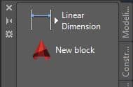
In a similar way drag and drop block from your drawing to the tool palette but make sure your drawing is saved before adding blocks to the palette.
To remove any tool from palette right-click on it and select delete from the contextual menu. Do not delete the drawing containing the block of tool palette otherwise the block will become inaccessible.
Adding custom icon to tools on the Palette:
You can add your own custom icon to the tool to give it a personal look. For that, you need an image in jpg, png, tiff, BMP or gif format. Right click on the tool for which you want to change the icon and select Specify image option from the contextual menu.
A new dialog box for selecting an image will appear with columns for selecting images for the light and dark theme. Select browse and locate image which you want to use for icon and click OK to close the specify images dialog box. Repeat the process for both light and dark theme images.
I am using AutoCAD logo in PNG format for my custom block, after modification, the tool looks like this.
Exporting and importing tool palette:
You can export this tool palette in a transferable format or you can also include this tool palette in the archive or e-transmit. For exporting this tool palette right-click in the blank area of tool palette and select customize palettes from the contextual menu. Alternatively, you can also use CUSTOMIZE command.
A new window will pop up with the list of all tool palettes listed on the left side of this window. Select your palette then right click and select export from the contextual menu.
A window will pop up where you need to specify a location for saving your tool palette or XTP file then click on save.
For importing any tool palette open customize window and right click on any tool from palettes panel of customize window and select import from the contextual menu. A new import palette window will pop up, locate your XTP file and click on open. Your new palette will be added to the list of existing palettes.
Do you have questions related to this tip? Let us know in the comments below.


 to turn it on, you can also turn on show annotation objects button to see a real-time effect of the change in scale on your drawing, see figure 6 for reference.


 appears in the status of most of the entities, these are resolved entities but there are also some entities shown with an exclamation mark
  which AutoCAD was not able to resolve and a “Not Found” button appears in the status of those unresolved entities.
 on the top of Reference manager window. You can also press and hold CTRL key to select multiple entities.
 indicating that the reference is now manually resolved.
 on the top of reference manager window.








 button on the top to align it towards the left side of the arc. Set the height of text as per your requirement using Text height field. See image below for reference.


 from the ArcAlignedText workshop window. The text on the concave side of the arc will look like image B as shown below.