Author: Jaiprakash Pandey

  • Making a linear array with copy command of AutoCAD

    Making a linear array with copy command of AutoCAD

    With the Array feature of the copy command, you can easily make a linear array in AutoCAD without using the rectangular array tool.

    To explain this feature I will use the geometry shown in the image below. Here we want to make an array of a verticle rectangle so that it finally looks like the image on the right side with six rectangles in a row with the gap of 2 units among each of them.

    array with copy command of AutoCAD
    Sample geometry for array

    Type CO on the command line and press enter to start the copy command then select rectangle and press enter again.

    Now specify any point on the rectangle as the base point, for this case I am clicking at lower left corner of the rectangle. Now look at the command line, it prompts you to select the second point or select the Array option.

    array with copy command of AutoCAD

    Select Array option from the command line, now it will prompt you to specify the number of items in the array. Type 6 on the command line and press enter. Command line will now prompt you to select the second point for the array or select the Fit option.

    Click at the second point in the drawing area to specify the gap between two corresponding array elements. You can also enter the distance between the two elements on the command line, for our current example, I will enter a distance of 2 units and press enter.

    You will see that an array will be created with six rectangles all spaced at the distance specified by you.

    Array with copy command in AutoCAD 3

    If you select the Fit option from the previous prompt then specifying a distance will fit all objects within that space. For example, if you select Fit and then type 10 on the command line and press enter then all six rectangles will be fitted in between a length of 10 units.

    Do you have questions related to this tip? Let me know in the comments below.

  • How to get high resolution images from AutoCAD drawings

    How to get high resolution images from AutoCAD drawings

    [fusion_builder_container hundred_percent=”no” equal_height_columns=”no” menu_anchor=”” hide_on_mobile=”small-visibility,medium-visibility,large-visibility” class=”” id=”” background_color=”” background_image=”” background_position=”center center” background_repeat=”no-repeat” fade=”no” background_parallax=”none” parallax_speed=”0.3″ video_mp4=”” video_webm=”” video_ogv=”” video_url=”” video_aspect_ratio=”16:9″ video_loop=”yes” video_mute=”yes” overlay_color=”” video_preview_image=”” border_size=”” border_color=”” border_style=”solid” padding_top=”” padding_bottom=”” padding_left=”” padding_right=”” admin_toggled=”no”][fusion_builder_row][fusion_builder_column type=”1_1″ layout=”1_1″ background_position=”left top” background_color=”” border_size=”” border_color=”” border_style=”solid” border_position=”all” spacing=”yes” background_image=”” background_repeat=”no-repeat” padding_top=”” padding_right=”” padding_bottom=”” padding_left=”” margin_top=”0px” margin_bottom=”0px” class=”” id=”” animation_type=”” animation_speed=”0.3″ animation_direction=”left” hide_on_mobile=”small-visibility,medium-visibility,large-visibility” center_content=”no” last=”no” min_height=”” hover_type=”none” link=””][fusion_text columns=”” column_min_width=”” column_spacing=”” rule_style=”default” rule_size=”” rule_color=”” hide_on_mobile=”small-visibility,medium-visibility,large-visibility” class=”” id=”” animation_type=”” animation_direction=”left” animation_speed=”0.3″ animation_offset=””]

    If you need high resolution images from AutoCAD drawings for presentation or printing purposes then this tip is for you. You need to configure plotter and paper settings for high resolution plot in AutoCAD, these settings are saved locally on the PC and they are not file dependent.

    Configuring plotter:

    To configure plotter type PLOTTERMANAGER on the command line and press enter. From Plotters window double click on Add-A-Plotter Wizard.

    Click Next in the wizard then select My Computer radio button from next page of the wizard and click Next again. From Plotter Model page select Raster file formats from manufacturers panel and TIFF version 6 (uncompressed) from models list.

    You can select other options also from Models panel like PNG and BMP but TIFF format will preserve layer data and other information as well in the image.

    Add plotter wizard

    Click on Next twice and select Plot to File radio button if prompted. Assign any name to your custom plotter, for this example, I am naming it as Custom Plotter. Click on Next button after assigning a name to the plotter.

    Click on Edit Plotter Configuration button from finish page of the wizard, this will open Plotter Configuration Editor for our custom plotter.edit plotter configuration

    Click on Device and Document Settings tab on this Plotter Configuration Editor window and expand User defined Paper Sizes & Calibration option and select Custom Paper Sizes then click on Add button to define new paper size, see the image below for reference.

    plotter configuration editor

    A new Custom Paper Size wizard will open, click Next button on the first page of this wizard. From Media Bounds page of the wizard enter 5000 in width and height fields as shown in the image below and click Next.

    high resolution images from AutoCAD

    Assign a name to the paper and keep all other settings at their default. For our example, I am naming it as Custom Size 5000 PX. Click on the finish button to close the Custom Paper Size wizard and also close all open windows.

    Now our plotter is fully configured for high-resolution plotting.

    Plotting in High resolution:

    Type PLOT on the command line and press enter this will open plot window. From this window select Custom Plotter.pc3 from printer/plotter drop down menu and select Custom Size 5000 px from Paper size drop down menu.

    Assign plot area and other settings and hit the OK button. This will make a high resolution TIFF image and its size may be very large compared to general image files.

    plot window

    Do you have questions related to this tip? Let me know in the comments below.

    [/fusion_text][/fusion_builder_column][/fusion_builder_row][/fusion_builder_container]

  • Search Objects like Blocks and Layers within AutoCAD drawings

    Search Objects like Blocks and Layers within AutoCAD drawings

    The search feature of design center can be used to search drawing and its components like block, layer, linetype and dimension style. This search tool can help you in locating drawings even if you don’t know its location or name simply by knowing its components name.

    let’s take an example where we need to find a block named bent_pipe but we don’t know the drawing which has this block.

    We can use the design center search feature to make this task easier and quick. Type CTRL+2 on keyboard and press enter alternatively you can also use its command equivalent ADCENTER. Once design center window appears, click on search on top of the design center window as shown in the image below.

    Search Objects like Blocks and Layers within AutoCAD drawings

    In the search window on the top left side, you will see “Look for” drop-down menu. Select component of drawing which you want to search. In this case, we want to search for bent_pipe block so select blocks from the drop down menu.

    Now browse to the folder or local/network drive where you believe drawing containing block under consideration is placed. Try to be as specific as possible in selecting the drive or folder to speed up the search.The time taken by this search to return the results will directly depend upon the number of drawing in the folder. More drawing will force it to crawl more resulting in delays.

    Click on search subfolders radio button also if you believe that drawing could be in any of the subfolders of the designated drive or folder.

    Type name of the object in Search field. In this case, we will enter bent_pipe as the name of the block and click on Search Now button. Your result will appear on the lower panel of search window with the path of drawing as shown in the image below.

    Search objects within AutoCAD drawings

    You can also use popular wildcard characters in the search field of the design center. As an example, if you want to find all blocks with name Door as the prefix then you can use Door* in the search field.

    You can directly use this block by double-clicking on it or by selecting Insert Block from right-click contextual menu.

    In a similar way, you can locate other components of a drawing using the search feature of the design center. If a drawing contains hundreds of layers, blocks or other components then you can use this tool to make a search within a drawing as well.

    You can use this tool to scan complete directories or drive also but as mentioned earlier, this search may take some time to complete so try to narrow down to the folder level to make a faster search.

    Do you have questions related to this tip? Let me know in the comments below.

  • How to change units in AutoCAD drawing

    How to change units in AutoCAD drawing

    [fusion_builder_container hundred_percent=”no” equal_height_columns=”no” menu_anchor=”” hide_on_mobile=”small-visibility,medium-visibility,large-visibility” class=”” id=”” background_color=”” background_image=”” background_position=”center center” background_repeat=”no-repeat” fade=”no” background_parallax=”none” parallax_speed=”0.3″ video_mp4=”” video_webm=”” video_ogv=”” video_url=”” video_aspect_ratio=”16:9″ video_loop=”yes” video_mute=”yes” overlay_color=”” video_preview_image=”” border_size=”” border_color=”” border_style=”solid” padding_top=”” padding_bottom=”” padding_left=”” padding_right=”” admin_toggled=”yes”][fusion_builder_row][fusion_builder_column type=”1_1″ layout=”1_1″ background_position=”left top” background_color=”” border_size=”” border_color=”” border_style=”solid” border_position=”all” spacing=”yes” background_image=”” background_repeat=”no-repeat” padding_top=”” padding_right=”” padding_bottom=”” padding_left=”” margin_top=”0px” margin_bottom=”0px” class=”” id=”” animation_type=”” animation_speed=”0.3″ animation_direction=”left” hide_on_mobile=”small-visibility,medium-visibility,large-visibility” center_content=”no” last=”no” min_height=”” hover_type=”none” link=””][fusion_text]

    In this article, I will explain two basic methods by which you can change units in AutoCAD drawing. I have also made this video to explain this tip in detail, In case you don’t prefer the video scroll below for the article.

    [/fusion_text][fusion_youtube id=”zcM6A5R6KRw” alignment=”center” width=”” height=”” autoplay=”false” api_params=”” hide_on_mobile=”small-visibility,medium-visibility,large-visibility” class=”” /][fusion_separator style_type=”none” hide_on_mobile=”small-visibility,medium-visibility,large-visibility” class=”” id=”” sep_color=”” top_margin=”30″ bottom_margin=”” border_size=”” icon=”” icon_circle=”” icon_circle_color=”” width=”” alignment=”center” /][fusion_text]

    Let’s assume that you have a drawing which is in imperial units (inches) and you want to convert it into metric units (mm), let’s name that drawing Sample.DWG.

    Using -DWGUNITS command:

    This is an easy method of converting the unit of drawing but it will work only for AutoCAD 2009 and later versions.

    Open Sample.DWG drawing (imperial) in AutoCAD and then type -DWGUNITS on the command line (don’t forget to add the dash before command) and press enter. Now, look at the command line prompt which looks like the image shown below.

    How to change units in AutoCAD

    Here you need to specify unit which you want to use in the current drawing, type the order number of unit and that unit will be applied. In this case, the millimeter option is in third place and hence typing 3 and pressing enter will select millimeter as drawing unit. Similarly, from other prompts use options as shown below.

    Linear display format    <2>

    Linear display precision   <4>

    Scale objects from other drawings upon insert?    <yes>

    Match INSUNITS to drawing units?    <yes>

    Depending on your selection you may or may not see following prompts on the command line. Select yes from both of these prompts.

    Scale objects in current drawing to reflect change in units? <yes>

    Include objects in Paper Space? <yes>

    Your drawing is now converted to metric with millimeter as drawing unit. You can verify the result by measuring the distance between any two points in the drawing, it will now be reported in millimeter instead of inches.

    Changing by block import:

    This method of converting unit is destructive in nature and you will lose a lot of data from your drawing, mostly named objects like layers, blocks, and linetypes.

    Open a new session of AutoCAD and click on New Drawing from the application menu, a template selection window will appear select acadiso.dwt template from this window and click open.

    how to convert mm to feet in autocad

    Now type UN on the command line and press enter Units window will appear. Select millimeters from Insertion Scale drop-down menu, you can select any other unit as well as per your own need but for this article, I will stick with millimeters.

    Now type I on the command line and press enter, browse your imperial unit drawing Sample.DWG from insert window.

    Uncheck Specify On-screen radio button from insertion point, Scale and Rotation panels, also make sure explode radio button is checked in the lower left corner of the Insert window.

    Convert units of drawing in AutoCAD

    If you have followed all these steps correctly then you will see a conversion factor of 25.4 in block unit panel now click OK to close the Insert window.

    Your drawing with converted units will be inserted into the new template and now if you check distances in drawing it will be reported in millimeter instead of original inches.

    Did you find this tip useful and which method you prefer to convert your drawings from one unit to other? Let me know in comments below.

    [/fusion_text][/fusion_builder_column][/fusion_builder_row][/fusion_builder_container]

  • How to make 2D from 3D drawing in AutoCAD

    How to make 2D from 3D drawing in AutoCAD

    [fusion_builder_container type=”legacy” hundred_percent=”no” hundred_percent_height=”no” min_height_medium=”” min_height_small=”” min_height=”” hundred_percent_height_scroll=”no” align_content=”stretch” flex_align_items=”flex-start” flex_justify_content=”flex-start” flex_column_spacing=”” hundred_percent_height_center_content=”yes” equal_height_columns=”no” container_tag=”div” menu_anchor=”” hide_on_mobile=”small-visibility,medium-visibility,large-visibility” status=”published” publish_date=”” class=”” id=”” margin_top_medium=”” margin_bottom_medium=”” margin_top_small=”” margin_bottom_small=”” margin_top=”” margin_bottom=”” padding_top_medium=”” padding_right_medium=”” padding_bottom_medium=”” padding_left_medium=”” padding_top_small=”” padding_right_small=”” padding_bottom_small=”” padding_left_small=”” padding_top=”” padding_right=”” padding_bottom=”” padding_left=”” link_hover_color=”var(–awb-color4)” hue=”” saturation=”” lightness=”” alpha=”” link_color=”var(–awb-color3)” border_sizes_top=”” border_sizes_right=”” border_sizes_bottom=”” border_sizes_left=”” border_color=”” border_style=”solid” border_radius_top_left=”” border_radius_top_right=”” border_radius_bottom_right=”” border_radius_bottom_left=”” box_shadow=”no” box_shadow_vertical=”” box_shadow_horizontal=”” box_shadow_blur=”0″ box_shadow_spread=”0″ box_shadow_color=”” box_shadow_style=”” z_index=”” overflow=”” gradient_start_color=”” gradient_end_color=”” gradient_start_position=”0″ gradient_end_position=”100″ gradient_type=”linear” radial_direction=”center center” linear_angle=”180″ background_color_medium=”” background_color_small=”” background_color=”” background_image_medium=”” background_image_small=”” background_image=”” skip_lazy_load=”” background_position_medium=”” background_position_small=”” background_position=”center center” background_repeat_medium=”” background_repeat_small=”” background_repeat=”no-repeat” background_size_medium=”” background_size_small=”” background_size=”” background_custom_size=”” background_custom_size_medium=”” background_custom_size_small=”” fade=”no” background_parallax=”none” enable_mobile=”no” parallax_speed=”0.3″ background_blend_mode_medium=”” background_blend_mode_small=”” background_blend_mode=”none” video_mp4=”” video_webm=”” video_ogv=”” video_url=”” video_aspect_ratio=”16:9″ video_loop=”yes” video_mute=”yes” video_preview_image=”” pattern_bg=”none” pattern_custom_bg=”” pattern_bg_color=”” pattern_bg_style=”default” pattern_bg_opacity=”100″ pattern_bg_size=”” pattern_bg_blend_mode=”normal” mask_bg=”none” mask_custom_bg=”” mask_bg_color=”” mask_bg_accent_color=”” mask_bg_style=”default” mask_bg_opacity=”100″ mask_bg_transform=”left” mask_bg_blend_mode=”normal” render_logics=”” absolute=”off” absolute_devices=”small,medium,large” sticky=”off” sticky_devices=”small-visibility,medium-visibility,large-visibility” sticky_background_color=”” sticky_height=”” sticky_offset=”” sticky_transition_offset=”0″ scroll_offset=”0″ animation_type=”” animation_direction=”left” animation_color=”” animation_speed=”0.3″ animation_delay=”0″ animation_offset=”” filter_hue=”0″ filter_saturation=”100″ filter_brightness=”100″ filter_contrast=”100″ filter_invert=”0″ filter_sepia=”0″ filter_opacity=”100″ filter_blur=”0″ filter_hue_hover=”0″ filter_saturation_hover=”100″ filter_brightness_hover=”100″ filter_contrast_hover=”100″ filter_invert_hover=”0″ filter_sepia_hover=”0″ filter_opacity_hover=”100″ filter_blur_hover=”0″ admin_toggled=”yes”][fusion_builder_row][fusion_builder_column type=”1_1″ layout=”1_1″ background_position=”left top” background_color=”” border_color=”” border_style=”solid” border_position=”all” spacing=”yes” background_image=”” background_repeat=”no-repeat” padding_top=”” padding_right=”” padding_bottom=”” padding_left=”” margin_top=”0px” margin_bottom=”0px” class=”” id=”” animation_type=”” animation_speed=”0.3″ animation_direction=”left” hide_on_mobile=”small-visibility,medium-visibility,large-visibility” center_content=”no” last=”true” min_height=”” hover_type=”none” link=”” border_sizes_top=”” border_sizes_bottom=”” border_sizes_left=”” border_sizes_right=”” first=”true”][fusion_text columns=”” column_min_width=”” column_spacing=”” rule_style=”” rule_size=”” rule_color=”” hue=”” saturation=”” lightness=”” alpha=”” content_alignment_medium=”” content_alignment_small=”” content_alignment=”” hide_on_mobile=”small-visibility,medium-visibility,large-visibility” sticky_display=”normal,sticky” class=”” id=”” margin_top=”” margin_right=”” margin_bottom=”” margin_left=”” fusion_font_family_text_font=”” fusion_font_variant_text_font=”” font_size=”” line_height=”” letter_spacing=”” text_transform=”” text_color=”” animation_type=”” animation_direction=”left” animation_color=”” animation_speed=”0.3″ animation_delay=”0″ animation_offset=””]

    There are at least two popular methods of converting 2D from 3D drawing in AutoCAD and these methods are using FLATSHOT command and using Layout views.

    In this article, I will show you both methods but I will start with the FLATSHOT command that will let you make the 2D drawing directly in the model space.

    Using FLATSHOT command

    I have also prepared this video to explain this method in detail, but if you prefer the article instead then read on.

    [fusion_youtube id=”PlS5rgVKjz8″ alignment=”center” width=”800″ height=”” autoplay=”false” api_params=”” title_attribute=”” video_facade=”” margin_top=”” margin_bottom=”” hide_on_mobile=”small-visibility,medium-visibility,large-visibility” class=”” css_id=”” structured_data=”off” video_upload_date=”” video_duration=”” video_title=”” video_desc=””][/fusion_youtube]

    This command can create 2D views like top, front, and isometric from a 3D model with just a few clicks directly in the model space.

    For explaining this command I will use this sample 3D drawing as shown in the following image, you can make a similar 3D drawing or use your own 3D drawing to follow along.
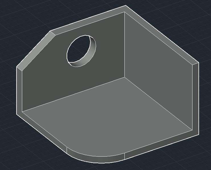
    Start AutoCAD and switch the visual style to “Shades of Gray” as shown in the following image so that the 3D model is clearly visible like the part shown above.

    Understanding the FLATSHOT dialogue box

    Select the FLATSHOT tool from the expanded “Section” panel of the “Home” tab or type FLATSHOT on the command line and press enter.

    The “Flatshot” dialogue box as shown in the following image will open, let’s have a look at the options of this dialogue box.
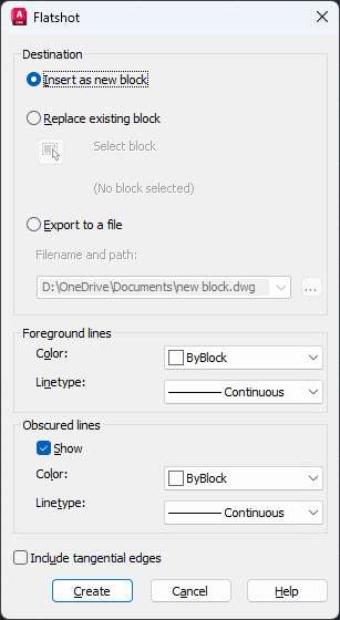
    Destination:

    The first option in the destination panel “Insert as new block” will ensure that new 2D views generated using Flatshot will be inserted as a block in the current drawing.

    The “Replace existing block” option will replace any block which you select with the 2D view created with the Flatshot tool.

    The third option “Export to a file” will export the 2D drawing to a new DWG file.

    Foreground line:

    These are the visible lines which are projected on the Top plane (also called the XY plane) along the current view which you have selected.

    You can set the color and linetype of the main 2D view using this option.

    Obscured line:

    These are hidden lines present in 2D geometry.

    If you want to show hidden lines then select the “Show” check box and change the color and Linetype of obscured or hidden lines from the drop-down menu.

    Include tangential edges:

    The last option is a checkbox mentioned as “Include tangential edges”.

    Checking this option will ensure that the tangential edges like fillets are also shown in the drawing, the following image shows the tangential edges clearly.

    2D from 3D drawing in AutoCAD

    Now that we know about the options of the Flastshot dialogue box let’s learn how we can use it to make 2D drawings using 3D.

    Creating Top View

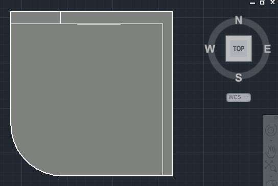
    In your View Cube set the current view to TOP so that the 3D part’s top view is only visible.

    In my case, setting the view to the Top on the View Cube will make the 3D drawing look like the following image.
    Select the Flatshot tool from the expanded section panel of the Home tab or type FLATSHOT on the command line and press enter key.

    Select “Insert as new block” in the Destination panel of the Flatshot dialogue box.

    Don’t change the properties of foreground lines and select the “Show” check box in the “Obscured lines” panel then change its color to green or anything else that you want.

    Also, change the linetype of obscured line to “Hidden” from the linetype option.
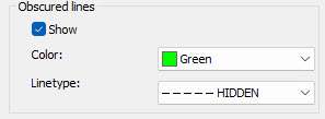
    Select the “Include tangential edges” check box and click Create.

    You will see the 2D drawing of the Top view of 3D geometry is now created and it follows the cursor.

    Click at a point in the drawing area preferably above the 3D drawing top view and press Enter key thrice to accept all default values.

    After adding the views my drawing looks like the following image.
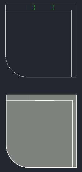
    In a similar way, you can make the other 2D views from the 3D drawing.

    Creating Front View

    Change your view to Front from the View cube or View drop-down menu so that the 3D drawing looks like the following image.
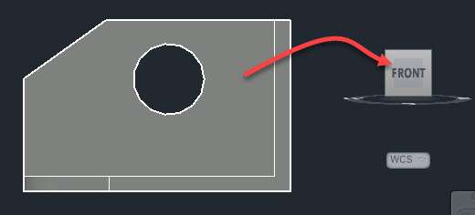
    Again start the FLATSHOT command.

    Select all the options from the Flatshot dialogue box just like in the previous example of the Top view and click on Create.

    In this case, also the 2D drawing of the Front view will follow the cursor but instead of a clear geometry, it will appear like a line because geometry is created on the top plane and we are on the front plane.

    So simply click near the 3D view and press the enter key thrice and the view will be generated on the top plane.

    Switch to the Top plane or the XY plane and you will be able to see the front view clearly like the image shown below.
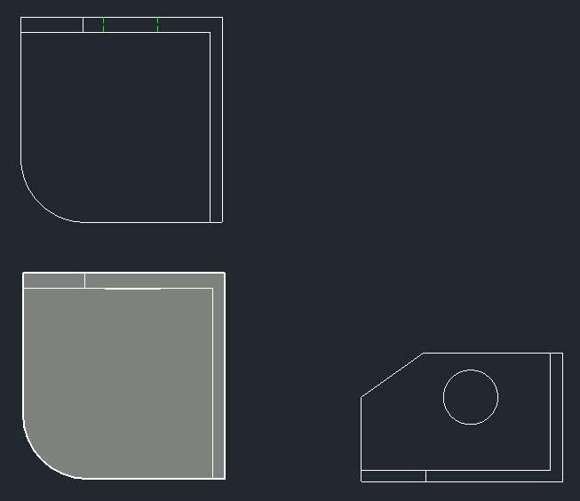
    The 2D drawing view generated may not be close to the 3D drawing, so you need to move it closer if it’s created far off.

    In this case, I moved it to the respective location like at the top of the drawing and on the right side.

    You can do that same once the 2D views are added in the drawing area.

    Creating Isometric view

    For creating the 2D isometric view from a 3D drawing change your view to SE isometric or any other isometric view which you like.

    In my case, the isometric view looks like the following image.

    Once again start the Flatshot command then use the same options we used in the previous two examples and place the view created at a location close to the 3D drawing and press enter key thrice.

    After rearranging all views created so far this is what my 2D drawing views look like.

    Now that you know how the Flatshot command can be used to make 2D views from 3D drawings let’s talk about another method that will let you convert 3D drawings into 2D in the layout view of AutoCAD.

    [/fusion_text][/fusion_builder_column][/fusion_builder_row][/fusion_builder_container][fusion_builder_container admin_label=”Course CTA” type=”flex” hundred_percent=”no” hundred_percent_height=”no” min_height_medium=”” min_height_small=”” min_height=”” hundred_percent_height_scroll=”no” align_content=”stretch” flex_align_items=”center” flex_justify_content=”center” flex_column_spacing=”” hundred_percent_height_center_content=”yes” equal_height_columns=”no” container_tag=”div” menu_anchor=”” hide_on_mobile=”small-visibility,medium-visibility,large-visibility” status=”published” publish_date=”” class=”” id=”” margin_top_medium=”” margin_bottom_medium=”” margin_top_small=”” margin_bottom_small=”” margin_top=”” margin_bottom=”” padding_top_medium=”” padding_right_medium=”” padding_bottom_medium=”” padding_left_medium=”” padding_top_small=”” padding_right_small=”” padding_bottom_small=”” padding_left_small=”” padding_top=”” padding_right=”” padding_bottom=”” padding_left=”” link_color=”” hue=”” saturation=”” lightness=”” alpha=”” link_hover_color=”” border_sizes_top=”” border_sizes_right=”” border_sizes_bottom=”” border_sizes_left=”” border_color=”” border_style=”solid” border_radius_top_left=”” border_radius_top_right=”” border_radius_bottom_right=”” border_radius_bottom_left=”” box_shadow=”no” box_shadow_vertical=”” box_shadow_horizontal=”” box_shadow_blur=”0″ box_shadow_spread=”0″ box_shadow_color=”” box_shadow_style=”” z_index=”” overflow=”” gradient_start_color=”” gradient_end_color=”” gradient_start_position=”0″ gradient_end_position=”100″ gradient_type=”linear” radial_direction=”center center” linear_angle=”180″ background_color=”” background_image=”” skip_lazy_load=”” background_position=”center center” background_repeat=”no-repeat” fade=”no” background_parallax=”none” enable_mobile=”no” parallax_speed=”0.3″ background_blend_mode=”none” video_mp4=”” video_webm=”” video_ogv=”” video_url=”” video_aspect_ratio=”16:9″ video_loop=”yes” video_mute=”yes” video_preview_image=”” pattern_bg=”none” pattern_custom_bg=”” pattern_bg_color=”” pattern_bg_style=”default” pattern_bg_opacity=”100″ pattern_bg_size=”” pattern_bg_blend_mode=”normal” mask_bg=”none” mask_custom_bg=”” mask_bg_color=”” mask_bg_accent_color=”” mask_bg_style=”default” mask_bg_opacity=”100″ mask_bg_transform=”left” mask_bg_blend_mode=”normal” render_logics=”” absolute=”off” absolute_devices=”small,medium,large” sticky=”off” sticky_devices=”small-visibility,medium-visibility,large-visibility” sticky_background_color=”” sticky_height=”” sticky_offset=”” sticky_transition_offset=”0″ scroll_offset=”0″ animation_type=”” animation_direction=”left” animation_color=”” animation_speed=”0.3″ animation_delay=”0″ animation_offset=”” filter_hue=”0″ filter_saturation=”100″ filter_brightness=”100″ filter_contrast=”100″ filter_invert=”0″ filter_sepia=”0″ filter_opacity=”100″ filter_blur=”0″ filter_hue_hover=”0″ filter_saturation_hover=”100″ filter_brightness_hover=”100″ filter_contrast_hover=”100″ filter_invert_hover=”0″ filter_sepia_hover=”0″ filter_opacity_hover=”100″ filter_blur_hover=”0″ admin_toggled=”yes”][fusion_builder_row][fusion_builder_column type=”1_1″ layout=”1_1″ align_self=”flex-start” content_layout=”column” align_content=”center” valign_content=”flex-start” content_wrap=”wrap” spacing=”” center_content=”no” column_tag=”div” link=”” target=”_self” link_description=”” min_height=”” hide_on_mobile=”small-visibility,medium-visibility,large-visibility” sticky_display=”normal,sticky” class=”” id=”” background_image_id=”” type_medium=”” type_small=”” order_medium=”0″ order_small=”0″ spacing_left_medium=”” spacing_right_medium=”” spacing_left_small=”” spacing_right_small=”” spacing_left=”” spacing_right=”” margin_top_medium=”” margin_bottom_medium=”” margin_top_small=”” margin_bottom_small=”” margin_top=”” margin_bottom=”” padding_top_medium=”” padding_right_medium=”” padding_bottom_medium=”” padding_left_medium=”” padding_top_small=”” padding_right_small=”” padding_bottom_small=”” padding_left_small=”” padding_top=”2%” padding_right=”2%” padding_bottom=”2%” padding_left=”2%” hover_type=”none” border_sizes_top=”” border_sizes_right=”” border_sizes_bottom=”” border_sizes_left=”” border_color=”” hue=”” saturation=”” lightness=”” alpha=”” border_style=”solid” border_radius_top_left=”10″ border_radius_top_right=”10″ border_radius_bottom_right=”10″ border_radius_bottom_left=”10″ box_shadow=”no” box_shadow_vertical=”” box_shadow_horizontal=”” box_shadow_blur=”0″ box_shadow_spread=”0″ box_shadow_color=”” box_shadow_style=”” z_index_subgroup=”regular” z_index=”” z_index_hover=”” overflow=”” background_type=”single” gradient_start_color=”” gradient_end_color=”” gradient_start_position=”0″ gradient_end_position=”100″ gradient_type=”linear” radial_direction=”center center” linear_angle=”180″ background_color=”var(–awb-color5)” background_image=”” lazy_load=”avada” skip_lazy_load=”” background_position=”left top” background_repeat=”no-repeat” background_blend_mode=”none” render_logics=”” sticky=”off” sticky_devices=”small-visibility,medium-visibility,large-visibility” sticky_offset=”” absolute=”off” absolute_top=”” absolute_right=”” absolute_bottom=”” absolute_left=”” filter_type=”regular” filter_hover_element=”self” filter_hue=”0″ filter_saturation=”100″ filter_brightness=”100″ filter_contrast=”100″ filter_invert=”0″ filter_sepia=”0″ filter_opacity=”100″ filter_blur=”0″ filter_hue_hover=”0″ filter_saturation_hover=”100″ filter_brightness_hover=”100″ filter_contrast_hover=”100″ filter_invert_hover=”0″ filter_sepia_hover=”0″ filter_opacity_hover=”100″ filter_blur_hover=”0″ transform_type=”regular” transform_hover_element=”self” transform_scale_x=”1″ transform_scale_y=”1″ transform_translate_x=”0″ transform_translate_y=”0″ transform_rotate=”0″ transform_skew_x=”0″ transform_skew_y=”0″ transform_origin=”” transform_scale_x_hover=”1″ transform_scale_y_hover=”1″ transform_translate_x_hover=”0″ transform_translate_y_hover=”0″ transform_rotate_hover=”0″ transform_skew_x_hover=”0″ transform_skew_y_hover=”0″ transition_duration=”300″ transition_easing=”ease” transition_custom_easing=”” animation_type=”” animation_direction=”left” animation_color=”” animation_speed=”0.3″ animation_delay=”0″ animation_offset=”” last=”true” border_position=”all” first=”true”][fusion_builder_row_inner][fusion_builder_column_inner type=”2_3″ layout=”2_3″ align_self=”center” content_layout=”column” align_content=”center” valign_content=”flex-start” content_wrap=”wrap” spacing=”” center_content=”no” column_tag=”div” link=”” target=”_self” link_description=”” min_height=”” hide_on_mobile=”small-visibility,medium-visibility,large-visibility” sticky_display=”normal,sticky” class=”” id=”” background_image_id=”” type_medium=”” type_small=”” order_medium=”0″ order_small=”0″ spacing_left_medium=”” spacing_right_medium=”” spacing_left_small=”” spacing_right_small=”” spacing_left=”6%” spacing_right=”” margin_top_medium=”” margin_bottom_medium=”” margin_top_small=”” margin_bottom_small=”” margin_top=”4%” margin_bottom=”4%” padding_top_medium=”” padding_right_medium=”” padding_bottom_medium=”” padding_left_medium=”” padding_top_small=”” padding_right_small=”” padding_bottom_small=”” padding_left_small=”” padding_top=”” padding_right=”” padding_bottom=”” padding_left=”2%” hover_type=”none” border_sizes_top=”” border_sizes_right=”” border_sizes_bottom=”” border_sizes_left=”” border_color=”” hue=”” saturation=”” lightness=”” alpha=”” border_style=”solid” border_radius_top_left=”” border_radius_top_right=”” border_radius_bottom_right=”” border_radius_bottom_left=”” box_shadow=”no” box_shadow_vertical=”” box_shadow_horizontal=”” box_shadow_blur=”0″ box_shadow_spread=”0″ box_shadow_color=”” box_shadow_style=”” overflow=”” background_type=”single” gradient_start_color=”” gradient_end_color=”” gradient_start_position=”0″ gradient_end_position=”100″ gradient_type=”linear” radial_direction=”center center” linear_angle=”180″ background_color=”” background_image=”” lazy_load=”avada” skip_lazy_load=”” background_position=”left top” background_repeat=”no-repeat” background_blend_mode=”none” render_logics=”” filter_type=”regular” filter_hue=”0″ filter_saturation=”100″ filter_brightness=”100″ filter_contrast=”100″ filter_invert=”0″ filter_sepia=”0″ filter_opacity=”100″ filter_blur=”0″ filter_hue_hover=”0″ filter_saturation_hover=”100″ filter_brightness_hover=”100″ filter_contrast_hover=”100″ filter_invert_hover=”0″ filter_sepia_hover=”0″ filter_opacity_hover=”100″ filter_blur_hover=”0″ animation_type=”” animation_direction=”left” animation_speed=”0.3″ animation_offset=”” last=”false” border_position=”all” first=”true”][fusion_text columns=”” column_min_width=”” column_spacing=”” rule_style=”” rule_size=”” rule_color=”” hue=”” saturation=”” lightness=”” alpha=”” content_alignment_medium=”” content_alignment_small=”” content_alignment=”” hide_on_mobile=”small-visibility,medium-visibility,large-visibility” sticky_display=”normal,sticky” class=”” id=”” margin_top=”” margin_right=”” margin_bottom=”” margin_left=”” fusion_font_family_text_font=”” fusion_font_variant_text_font=”” font_size=”” line_height=”” letter_spacing=”” text_transform=”none” text_color=”var(–awb-color8)” animation_type=”” animation_direction=”left” animation_color=”” animation_speed=”0.3″ animation_delay=”0″ animation_offset=””]

    Learn AutoCAD right from scratch with video courses by published Authors

    [/fusion_text][fusion_button link=”https://thesourcecad.com/autocad-courses/” title=”” target=”_self” link_attributes=”” alignment_medium=”” alignment_small=”” alignment=”left” modal=”” hide_on_mobile=”small-visibility,medium-visibility,large-visibility” sticky_display=”normal,sticky” class=”” id=”” color=”custom” button_gradient_top_color_hover=”var(–awb-color4)” hue=”” saturation=”” lightness=”” alpha=”” button_gradient_top_color=”var(–awb-color3)” button_gradient_bottom_color_hover=”var(–awb-color4)” button_gradient_bottom_color=”var(–awb-color3)” gradient_start_position=”” gradient_end_position=”” gradient_type=”” radial_direction=”” linear_angle=”180″ accent_hover_color=”” accent_color=”” type=”flat” bevel_color=”” bevel_color_hover=”” border_top=”” border_right=”” border_bottom=”” border_left=”” border_radius_top_left=”” border_radius_top_right=”” border_radius_bottom_right=”” border_radius_bottom_left=”” border_hover_color=”” border_color=”” size=”large” padding_top=”” padding_right=”” padding_bottom=”” padding_left=”” fusion_font_family_button_font=”” fusion_font_variant_button_font=”” font_size=”” line_height=”” letter_spacing=”” text_transform=”” stretch=”no” margin_top=”” margin_right=”” margin_bottom=”” margin_left=”” icon=”” icon_position=”left” icon_divider=”no” hover_transition=”none” animation_type=”” animation_direction=”left” animation_color=”” animation_speed=”0.3″ animation_delay=”0″ animation_offset=””]Check Course Details[/fusion_button][/fusion_builder_column_inner][fusion_builder_column_inner type=”1_3″ layout=”1_3″ align_self=”center” content_layout=”column” align_content=”center” valign_content=”flex-start” content_wrap=”wrap” spacing=”” center_content=”yes” column_tag=”div” link=”” target=”_self” link_description=”” min_height=”” hide_on_mobile=”large-visibility” sticky_display=”normal,sticky” class=”” id=”” background_image_id=”” type_medium=”” type_small=”” order_medium=”0″ order_small=”0″ spacing_left_medium=”” spacing_right_medium=”” spacing_left_small=”” spacing_right_small=”” spacing_left=”” spacing_right=”” margin_top_medium=”” margin_bottom_medium=”” margin_top_small=”” margin_bottom_small=”” margin_top=”” margin_bottom=”” padding_top_medium=”” padding_right_medium=”” padding_bottom_medium=”” padding_left_medium=”” padding_top_small=”” padding_right_small=”” padding_bottom_small=”” padding_left_small=”” padding_top=”” padding_right=”” padding_bottom=”” padding_left=”” hover_type=”none” border_sizes_top=”” border_sizes_right=”” border_sizes_bottom=”” border_sizes_left=”” border_color=”” hue=”” saturation=”” lightness=”” alpha=”” border_style=”solid” border_radius_top_left=”” border_radius_top_right=”” border_radius_bottom_right=”” border_radius_bottom_left=”” box_shadow=”no” box_shadow_vertical=”” box_shadow_horizontal=”” box_shadow_blur=”0″ box_shadow_spread=”0″ box_shadow_color=”” box_shadow_style=”” z_index_subgroup=”regular” z_index=”” z_index_hover=”” overflow=”” background_type=”single” gradient_start_color=”” gradient_end_color=”” gradient_start_position=”0″ gradient_end_position=”100″ gradient_type=”linear” radial_direction=”center center” linear_angle=”180″ background_color=”” background_image=”” lazy_load=”avada” skip_lazy_load=”” background_position=”left top” background_repeat=”no-repeat” background_blend_mode=”none” render_logics=”” sticky=”off” sticky_devices=”small-visibility,medium-visibility,large-visibility” sticky_offset=”” absolute=”off” absolute_top=”” absolute_right=”” absolute_bottom=”” absolute_left=”” filter_type=”regular” filter_hover_element=”self” filter_hue=”0″ filter_saturation=”100″ filter_brightness=”100″ filter_contrast=”100″ filter_invert=”0″ filter_sepia=”0″ filter_opacity=”100″ filter_blur=”0″ filter_hue_hover=”0″ filter_saturation_hover=”100″ filter_brightness_hover=”100″ filter_contrast_hover=”100″ filter_invert_hover=”0″ filter_sepia_hover=”0″ filter_opacity_hover=”100″ filter_blur_hover=”0″ transform_type=”regular” transform_hover_element=”self” transform_scale_x=”1″ transform_scale_y=”1″ transform_translate_x=”0″ transform_translate_y=”0″ transform_rotate=”0″ transform_skew_x=”0″ transform_skew_y=”0″ transform_origin=”” transform_scale_x_hover=”1″ transform_scale_y_hover=”1″ transform_translate_x_hover=”0″ transform_translate_y_hover=”0″ transform_rotate_hover=”0″ transform_skew_x_hover=”0″ transform_skew_y_hover=”0″ transition_duration=”300″ transition_easing=”ease” transition_custom_easing=”” animation_type=”” animation_direction=”left” animation_color=”” animation_speed=”0.3″ animation_delay=”0″ animation_offset=”” last=”true” border_position=”all” first=”false”][fusion_imageframe image_id=”25502|full” aspect_ratio=”” custom_aspect_ratio=”100″ aspect_ratio_position=”” skip_lazy_load=”” lightbox=”no” gallery_id=”” lightbox_image=”” lightbox_image_id=”” alt=”” link=”” linktarget=”_self” hide_on_mobile=”small-visibility,medium-visibility,large-visibility” sticky_display=”normal,sticky” class=”” id=”” max_width=”” sticky_max_width=”” align_medium=”none” align_small=”none” align=”center” mask=”” custom_mask=”” mask_size=”” mask_custom_size=”” mask_position=”” mask_custom_position=”” mask_repeat=”” style_type=”” blur=”” stylecolor=”” hue=”” saturation=”” lightness=”” alpha=”” hover_type=”none” margin_top_medium=”” margin_right_medium=”” margin_bottom_medium=”” margin_left_medium=”” margin_top_small=”” margin_right_small=”” margin_bottom_small=”” margin_left_small=”” margin_top=”” margin_right=”” margin_bottom=”” margin_left=”” bordersize=”” bordercolor=”” borderradius=”” z_index=”” caption_style=”off” caption_align_medium=”none” caption_align_small=”none” caption_align=”none” caption_title=”” caption_text=”” caption_title_tag=”2″ fusion_font_family_caption_title_font=”” fusion_font_variant_caption_title_font=”” caption_title_size=”” caption_title_line_height=”” caption_title_letter_spacing=”” caption_title_transform=”” caption_title_color=”” caption_background_color=”” fusion_font_family_caption_text_font=”” fusion_font_variant_caption_text_font=”” caption_text_size=”” caption_text_line_height=”” caption_text_letter_spacing=”” caption_text_transform=”” caption_text_color=”” caption_border_color=”” caption_overlay_color=”” caption_margin_top=”” caption_margin_right=”” caption_margin_bottom=”” caption_margin_left=”” animation_type=”” animation_direction=”left” animation_color=”” animation_speed=”0.3″ animation_delay=”0″ animation_offset=”” filter_hue=”0″ filter_saturation=”100″ filter_brightness=”100″ filter_contrast=”100″ filter_invert=”0″ filter_sepia=”0″ filter_opacity=”100″ filter_blur=”0″ filter_hue_hover=”0″ filter_saturation_hover=”100″ filter_brightness_hover=”100″ filter_contrast_hover=”100″ filter_invert_hover=”0″ filter_sepia_hover=”0″ filter_opacity_hover=”100″ filter_blur_hover=”0″]https://thesourcecad.com/wp-content/uploads/2014/10/Courses-new.png[/fusion_imageframe][/fusion_builder_column_inner][/fusion_builder_row_inner][/fusion_builder_column][/fusion_builder_row][/fusion_builder_container][fusion_builder_container type=”flex” hundred_percent=”no” hundred_percent_height=”no” min_height_medium=”” min_height_small=”” min_height=”” hundred_percent_height_scroll=”no” align_content=”stretch” flex_align_items=”flex-start” flex_justify_content=”flex-start” flex_column_spacing=”” hundred_percent_height_center_content=”yes” equal_height_columns=”no” container_tag=”div” menu_anchor=”” hide_on_mobile=”small-visibility,medium-visibility,large-visibility” status=”published” publish_date=”” class=”” id=”” margin_top_medium=”” margin_bottom_medium=”” margin_top_small=”” margin_bottom_small=”” margin_top=”” margin_bottom=”” padding_top_medium=”” padding_right_medium=”” padding_bottom_medium=”” padding_left_medium=”” padding_top_small=”” padding_right_small=”” padding_bottom_small=”” padding_left_small=”” padding_top=”” padding_right=”” padding_bottom=”” padding_left=”” link_hover_color=”” hue=”” saturation=”” lightness=”” alpha=”” link_color=”var(–awb-color3)” border_sizes_top=”” border_sizes_right=”” border_sizes_bottom=”” border_sizes_left=”” border_color=”” border_style=”solid” border_radius_top_left=”” border_radius_top_right=”” border_radius_bottom_right=”” border_radius_bottom_left=”” box_shadow=”no” box_shadow_vertical=”” box_shadow_horizontal=”” box_shadow_blur=”0″ box_shadow_spread=”0″ box_shadow_color=”” box_shadow_style=”” z_index=”” overflow=”” gradient_start_color=”” gradient_end_color=”” gradient_start_position=”0″ gradient_end_position=”100″ gradient_type=”linear” radial_direction=”center center” linear_angle=”180″ background_color_medium=”” background_color_small=”” background_color=”” background_image_medium=”” background_image_small=”” background_image=”” skip_lazy_load=”” background_position_medium=”” background_position_small=”” background_position=”center center” background_repeat_medium=”” background_repeat_small=”” background_repeat=”no-repeat” background_size_medium=”” background_size_small=”” background_size=”” background_custom_size=”” background_custom_size_medium=”” background_custom_size_small=”” fade=”no” background_parallax=”none” enable_mobile=”no” parallax_speed=”0.3″ background_blend_mode_medium=”” background_blend_mode_small=”” background_blend_mode=”none” video_mp4=”” video_webm=”” video_ogv=”” video_url=”” video_aspect_ratio=”16:9″ video_loop=”yes” video_mute=”yes” video_preview_image=”” pattern_bg=”none” pattern_custom_bg=”” pattern_bg_color=”” pattern_bg_style=”default” pattern_bg_opacity=”100″ pattern_bg_size=”” pattern_bg_blend_mode=”normal” mask_bg=”none” mask_custom_bg=”” mask_bg_color=”” mask_bg_accent_color=”” mask_bg_style=”default” mask_bg_opacity=”100″ mask_bg_transform=”left” mask_bg_blend_mode=”normal” render_logics=”” absolute=”off” absolute_devices=”small,medium,large” sticky=”off” sticky_devices=”small-visibility,medium-visibility,large-visibility” sticky_background_color=”” sticky_height=”” sticky_offset=”” sticky_transition_offset=”0″ scroll_offset=”0″ animation_type=”” animation_direction=”left” animation_color=”” animation_speed=”0.3″ animation_delay=”0″ animation_offset=”” filter_hue=”0″ filter_saturation=”100″ filter_brightness=”100″ filter_contrast=”100″ filter_invert=”0″ filter_sepia=”0″ filter_opacity=”100″ filter_blur=”0″ filter_hue_hover=”0″ filter_saturation_hover=”100″ filter_brightness_hover=”100″ filter_contrast_hover=”100″ filter_invert_hover=”0″ filter_sepia_hover=”0″ filter_opacity_hover=”100″ filter_blur_hover=”0″ admin_toggled=”yes”][fusion_builder_row][fusion_builder_column type=”1_1″ layout=”1_1″ align_self=”auto” content_layout=”column” align_content=”flex-start” valign_content=”flex-start” content_wrap=”wrap” spacing=”” center_content=”no” column_tag=”div” link=”” target=”_self” link_description=”” min_height=”” hide_on_mobile=”small-visibility,medium-visibility,large-visibility” sticky_display=”normal,sticky” class=”” id=”” type_medium=”” type_small=”” order_medium=”0″ order_small=”0″ dimension_spacing_medium=”” dimension_spacing_small=”” dimension_spacing=”” dimension_margin_medium=”” dimension_margin_small=”” margin_top=”” margin_bottom=”” padding_medium=”” padding_small=”” padding_top=”” padding_right=”” padding_bottom=”” padding_left=”” hover_type=”none” border_sizes=”” border_color_hover=”” border_color=”” border_style=”solid” border_radius=”” box_shadow=”no” dimension_box_shadow=”” box_shadow_blur=”0″ box_shadow_spread=”0″ box_shadow_color=”” box_shadow_style=”” z_index_hover=”” z_index=”” overflow=”” background_type=”single” gradient_start_color=”” gradient_end_color=”” gradient_start_position=”0″ gradient_end_position=”100″ gradient_type=”linear” radial_direction=”center center” linear_angle=”180″ background_color_medium=”” background_color_small=”” background_color_hover=”” background_color=”” background_image_medium=”” background_image_small=”” background_image=”” background_image_id_medium=”” background_image_id_small=”” background_image_id=”” lazy_load=”avada” skip_lazy_load=”” background_position_medium=”” background_position_small=”” background_position=”left top” background_repeat_medium=”” background_repeat_small=”” background_repeat=”no-repeat” background_size_medium=”” background_size_small=”” background_size=”” background_custom_size=”” background_custom_size_medium=”” background_custom_size_small=”” background_blend_mode_medium=”” background_blend_mode_small=”” background_blend_mode=”none” render_logics=”” sticky=”off” sticky_devices=”small-visibility,medium-visibility,large-visibility” sticky_offset=”” absolute=”off” absolute_props=”” filter_type=”regular” filter_hover_element=”self” filter_hue=”0″ filter_saturation=”100″ filter_brightness=”100″ filter_contrast=”100″ filter_invert=”0″ filter_sepia=”0″ filter_opacity=”100″ filter_blur=”0″ filter_hue_hover=”0″ filter_saturation_hover=”100″ filter_brightness_hover=”100″ filter_contrast_hover=”100″ filter_invert_hover=”0″ filter_sepia_hover=”0″ filter_opacity_hover=”100″ filter_blur_hover=”0″ transform_type=”regular” transform_hover_element=”self” transform_scale_x=”1″ transform_scale_y=”1″ transform_translate_x=”0″ transform_translate_y=”0″ transform_rotate=”0″ transform_skew_x=”0″ transform_skew_y=”0″ transform_scale_x_hover=”1″ transform_scale_y_hover=”1″ transform_translate_x_hover=”0″ transform_translate_y_hover=”0″ transform_rotate_hover=”0″ transform_skew_x_hover=”0″ transform_skew_y_hover=”0″ transform_origin=”” transition_duration=”300″ transition_easing=”ease” transition_custom_easing=”” motion_effects=”” scroll_motion_devices=”small-visibility,medium-visibility,large-visibility” animation_type=”” animation_direction=”left” animation_color=”” animation_speed=”0.3″ animation_delay=”0″ animation_offset=”” last=”true” border_position=”all” first=”true”][fusion_text columns=”” column_min_width=”” column_spacing=”” rule_style=”” rule_size=”” rule_color=”” hue=”” saturation=”” lightness=”” alpha=”” content_alignment_medium=”” content_alignment_small=”” content_alignment=”” hide_on_mobile=”small-visibility,medium-visibility,large-visibility” sticky_display=”normal,sticky” class=”” id=”” margin_top=”” margin_right=”” margin_bottom=”” margin_left=”” fusion_font_family_text_font=”” fusion_font_variant_text_font=”” font_size=”” line_height=”” letter_spacing=”” text_transform=”” text_color=”” animation_type=”” animation_direction=”left” animation_color=”” animation_speed=”0.3″ animation_delay=”0″ animation_offset=””]

    Using Layout View to Convert 3D into 2D

    This is the method that you should use if you want to use the layout view of AutoCAD to generate the 2D views from your 3D drawings.

    For this example as well I will use the same drawing that I used for the Flatshot command.

    So, start the drawing and change the visual style to “Shades of Grey” and remove any 2D drawings from the drawing if there are any.

    Now switch to the layout view using the “Layout 1” tab on the bottom left corner of the drawing view.
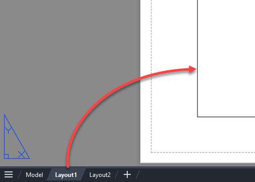
    Now a white layout with a rectangular box with your 3D drawing in it will show up, delete this rectangular box.

    Now go to the Layout tab and select the “From model space” option from the “Create view” panel as shown in the following image.

    AutoCAD may take a few seconds to process this drawing and after a few seconds, the drawing’s front view will show up on your cursor.

    Click at a location on the layout to place this front view and then press enter key.

    The front view will be added and now you can move your cursor above the drawing to place the top view.

    After that move to the left to create the left-side view and move to the top left corner to make the isometric view.

    Once you are done making the views press the enter key and AutoCAD will instantly generate the 2D views from your 3D drawings as shown in the following animated image.

    Depending on the drafting standard first angle and third angle projection system your view placement may change but more or less it will remain the same as shown in the example above.

    Now you can add more details like dimensions and other annotations in this view as well.

    One important thing about 2D views created here is that they are linked with the 3D drawing so if you later decide to change the 3D drawing or modify its features the 2D views will change automatically.

    Conclusion

    As you can see there are two easy methods of converting 3D drawing to 2D in AutoCAD and both are easy and straightforward.

    The first method of using the Flatshot command will help you make the 2D from 3D in model space and the second method will help you make it in Layout space.

    Let me know in the comments if you are using these methods.

    [/fusion_text][/fusion_builder_column][/fusion_builder_row][/fusion_builder_container]

  • Six useful AutoCAD command line tips

    Six useful AutoCAD command line tips

    AutoCAD command line may look very insignificant to new users but it’s rather very useful tool and it can increase your productivity in many ways. Here I will introduce you to some of the features of the command line that can increase your overall productivity with the software.

    Customizing size of the command line:

    Command line is an AutoCAD palette and you can change its size by expanding it using your cursor, you can also move this command line by holding top left corner with the cursor.

    By default, two lines are visible above command line which shows recently entered commands you can expand or collapse its size to show more or less number of lines in the command history.

    default autocad 2015 command line

    Hiding and bringing back command line:

    Sometimes users accidentally turn off command line and then it becomes annoying to find no option for bringing it back. You can use CTRL+9 shortcut key combination to toggle the visibility of command line.

    Looking at command history:

    On pressing the F2 key a pop-up will appear above command line with a list of all recently used commands and inputs. To insert a command from this list highlight it and then right-click a contextual menu will appear select Paste to Command line from this menu.

    You can also use UP and DOWN arrow key to toggle previously used commands when the desired command appears on command line press enter to select it.

    Turning on/off command auto-complete:

    Starting from AutoCAD 2012 there is an auto-complete feature added to AutoCAD. When you type a command you will see a list of suggested commands starting with the letters as you type it and this list becomes more and more specific as you enter more letters on the command line.

    This feature can be great for finding the correct command but if you find this annoying then you can turn it off also.

    For turning auto-complete off type INPUTSEARCHOPTIONS on the command line and uncheck the radio button in the Auto-complete panel as shown in the image below.

    Six useful AutoCAD command-line tips

    Searching and using named objects:

    You can use the command line to search named objects like blocks, layer, dimension style etc directly without looking for them at the respective place.

    Let’s assume that we have a drawing with a layer named DOOR and a block named DOOR so if you type DOOR in the command line you will see that AutoCAD will suggest you two options one for block and other for layer DOOR.

    Six useful AutoCAD command-line tips

    Selecting any named object from the command line will make it the current object for the drawing. For example on selecting DOOR layer from these options, it will become the current layer.

    If you want to turn off this search feature then uncheck the “Search content at command line” radio button from input search options window as mentioned in the tip above.

    Autocorrecting spelling mistakes in command:

    If you are the one who makes frequent spelling mistakes of command then this feature is for you.

    Go to Customization panel of Manage tab and select Edit AutoCorrect list from Edit Aliases drop-down menu of Customization panel. A PGP file will open with notepad and you can enter your own misspellings in it.

    Six useful AutoCAD command-line tips

    For example, let’s assume you make a frequent spelling mistake of typing LAYER as LEAR then you can enter this misspelling in the PGP file so that even when you enter misspelling it will enter correct spelling.

    The incorrect spelling should be entered first followed by a comma and then the correct spelling prefixed with asterisk, here is an example LEAR, *LAYER

    Here the first spelling is incorrect and second is correct one. Once you have entered misspellings save PGP file and exit it. You may need to restart session of AutoCAD after applying these settings.

    Which of the above tips do you find most useful? let us know in the comments below.

  • Migrate custom settings of AutoCAD using profiles

    Migrate custom settings of AutoCAD using profiles

    Drafters generally have their own set of custom AutoCAD settings like default project file paths, template locations, linetypes, hatch patterns and printer defaults.

    When you change your workstation these settings need to be manually configured again in the software. But if you save these settings in your own custom profile then the settings can be transferred directly to a new workstation.

    Creating your own Profile:

    To save the settings you need a user profile in the AutoCAD. To create a user profile type OP on the command line and press enter. The options window will pop up, in this window select profiles tab as shown in the image below.

    Migrate custom settings of AutoCAD

    Here you will see Unnamed Profile in the list of available profiles which is the default profile, other profiles may also be present depending upon your previous settings.

    In this example, I will create our own profile with name Custom profile. Click Add to List button from the right panel of Profiles tab, enter a name and click Apply & close button.

    Now in order to make this profile current select it from profile list and click set current button. You will notice that name of this profile will appear on the top left of options window as shown in the image below.

    Migrate custom settings of AutoCAD

    The Custom profile is now ready for saving your custom settings, this profile will save your settings to your local drive. These settings are saved with ARG file extension and you can open this file using notepad.

    Migrating profile to other PC:

    You can export profile as ARG file from your workstation and import it in another PC to apply all your custom settings automatically.

    To export this Custom profile type OP on the command line press enter and select profiles tab from options window. Now click on Custom profile from the list of profiles and click on the Export button as shown in the image below.

    Migrate custom settings of AutoCAD

    Specify a location where you want to save your profile then give it a name. For the current example I have named it as Custom Profile, click on save button. You will notice that an ARG file will be created at the specified location.

    To use this profile in other workstations copy it there and click import on profiles tab of the options window then locate the file and click open. The Custom profile will be added to the list of available profiles. Set this profile as current and all custom settings will be replaced by the settings stored in Custom profile.

    Do you have questions related to this tip? Let me know in the comments below.

  • How to import and export a table from AutoCAD to Excel

    How to import and export a table from AutoCAD to Excel

    [fusion_builder_container hundred_percent=”no” equal_height_columns=”no” menu_anchor=”” hide_on_mobile=”small-visibility,medium-visibility,large-visibility” class=”” id=”” background_color=”” background_image=”” background_position=”center center” background_repeat=”no-repeat” fade=”no” background_parallax=”none” parallax_speed=”0.3″ video_mp4=”” video_webm=”” video_ogv=”” video_url=”” video_aspect_ratio=”16:9″ video_loop=”yes” video_mute=”yes” overlay_color=”” video_preview_image=”” border_size=”” border_color=”” border_style=”solid” padding_top=”” padding_bottom=”” padding_left=”” padding_right=”” admin_toggled=”no”][fusion_builder_row][fusion_builder_column type=”1_1″ layout=”1_1″ background_position=”left top” background_color=”” border_size=”” border_color=”” border_style=”solid” border_position=”all” spacing=”yes” background_image=”” background_repeat=”no-repeat” padding_top=”” padding_right=”” padding_bottom=”” padding_left=”” margin_top=”0px” margin_bottom=”0px” class=”” id=”” animation_type=”” animation_speed=”0.3″ animation_direction=”left” hide_on_mobile=”small-visibility,medium-visibility,large-visibility” center_content=”no” last=”no” min_height=”” hover_type=”none” link=””][fusion_text columns=”” column_min_width=”” column_spacing=”” rule_style=”default” rule_size=”” rule_color=”” hide_on_mobile=”small-visibility,medium-visibility,large-visibility” class=”” id=”” animation_type=”” animation_direction=”left” animation_speed=”0.3″ animation_offset=””]

    In this article, I will explain methods by which you can import and export a table from AutoCAD to Excel. Let’s first start with importing a table.

    Importing the table in AutoCAD:

    In AutoCAD, you can import excel table as OLE object which is linked to its original source or as an independent AutoCAD table where it is not linked to its parent table. In this article, I will use this sample table made in MS- Excel to demonstrate how this process works.

    import and export table from AutoCAD to Excel

    Importing as a data link:

    Open excel file downloaded from the link above and select table completely then right click and select copy from the contextual menu, you can also use CTRL+C to copy table. Now open AutoCAD and click on paste special from clipboard panel of the home tab as shown in the image below.

    import and export table from AutoCAD to Excel

    Paste special window will pop up, in this window select Paste Link radio button and click on the Microsoft Excel Worksheet option and click OK. Now specify a location in the drawing area to paste this table.

    The table will now appear in drawing area just like any other Excel table.This table will retain its formatting like line width and cell merges and it will also remain linked with its parent table from where it is copied.

    Now open MS-Excel table and make any change in it and save it then go to AutoCAD window and type REA to regenerate your drawing and you will see that table is updated in AutoCAD too with changed value.

    Importing as AutoCAD entity:

    You can also import table in AutoCAD as a standalone entity so that it remains completely isolated from excel table.

    import and export a table from AutoCAD to Excel

    Repeat the whole process of copying table from MS-Excel and select paste special again from clipboard panel of the home tab but this time select AutoCAD entities option from the Paste Special window and click OK.

    Now specify a location to paste your table in the drawing area. The table will be inserted as an AutoCAD entity and it will retain its formatting too.

    In this case, you will observe that table has no relation to its parent MS-Excel table and any change made to that parent table will no longer be reflected in the AutoCAD table.

    Exporting table from AutoCAD:

    You can export a table from AutoCAD in a format like CSV which can be read by the MS office application.

    import and export a table from AutoCAD to Excel

    Table exported from AutoCAD does not retain its formatting which means cell color, cell merging, and border styles are not retained in CSV format and after exporting you need to again add formatting to the table if required.

    To export a table select it completely then right click and select Export from the contextual menu, Export data window will pop up. Now name your table and provide a location where you want to save it and click save.

    A new table in CSV format will be saved at the specified location, this table can now be opened with MS-office and other CSV compatible applications.

    Do you have questions related to this tip? let us know in the comments below.

    [/fusion_text][/fusion_builder_column][/fusion_builder_row][/fusion_builder_container]

  • What is the Defpoints layer in AutoCAD

    What is the Defpoints layer in AutoCAD

    [fusion_builder_container hundred_percent=”no” equal_height_columns=”no” menu_anchor=”” hide_on_mobile=”small-visibility,medium-visibility,large-visibility” class=”” id=”” background_color=”” background_image=”” background_position=”center center” background_repeat=”no-repeat” fade=”no” background_parallax=”none” parallax_speed=”0.3″ video_mp4=”” video_webm=”” video_ogv=”” video_url=”” video_aspect_ratio=”16:9″ video_loop=”yes” video_mute=”yes” overlay_color=”” video_preview_image=”” border_size=”” border_color=”” border_style=”solid” padding_top=”” padding_bottom=”” padding_left=”” padding_right=”” admin_toggled=”yes”][fusion_builder_row][fusion_builder_column type=”1_1″ layout=”1_1″ background_position=”left top” background_color=”” border_size=”” border_color=”” border_style=”solid” border_position=”all” spacing=”yes” background_image=”” background_repeat=”no-repeat” padding_top=”” padding_right=”” padding_bottom=”” padding_left=”” margin_top=”0px” margin_bottom=”0px” class=”” id=”” animation_type=”” animation_speed=”0.3″ animation_direction=”left” hide_on_mobile=”small-visibility,medium-visibility,large-visibility” center_content=”no” last=”no” min_height=”” hover_type=”none” link=””][fusion_text]

    You must have noticed Defpoints layer in layer property manager of AutoCAD which is automatically created. Have you wondered why this layer is created automatically and what is the use of this layer, keep reading this article to get answers.

    What is Defpoints layer?

    This layer is automatically generated when a dimension is created in your AutoCAD drawing, this layer stores information about definition points of dimensions. Objects on this layer are visible in drawing area but these objects will not appear when you plot your drawing, plotting is turned off for Defpoints layer.

    What is Defpoints layer
    Fig 1 – Defpoints as seen in dimensions

    Definition points are reference points for dimensions these are same points which appear at grip location when a dimension is selected. In the image above you will notice tiny points at the location of red circles, these points are visible only in the drawing area and they are never plotted.

    A Defpoint layer cannot be deleted and if you try to delete it then an error message will appear as shown in figure 2. Although LAYDEL command can be used to delete this layer but I would not recommend it as it may corrupt your drawing.

    What is Defpoints layer
    Fig 2 – Defpoint layer and error message

    Should I place objects on Defpoints layer?

    Drafters generally harness this property of Defpoints layer to place objects on this layer which they don’t want to plot for example viewports and construction geometries but it is not a good practice as it may lead to unexpected changes in drawing such as.

    If you freeze layer 0 then anything placed on Defpoints layer will become partially locked and you will not be able to select objects on it.

    On running AUDIT command all objects placed on Defpoints layer will be transferred to a new layer $AUDIT-BAD-LAYER and as a result, objects will remain visible in the plot.

    So try to always create a new layer with its plot turned off and then place all objects which you don’t want to show in the plot like viewport and construction geometries on that layer.

    How you use Defpoints layer and do you also use it for placing no-plot objects? Let me know in the comments below.

    [/fusion_text][/fusion_builder_column][/fusion_builder_row][/fusion_builder_container]

  • How to create custom material in AutoCAD from scratch

    How to create custom material in AutoCAD from scratch

    [fusion_builder_container type=”flex” hundred_percent=”no” hundred_percent_height=”no” min_height_medium=”” min_height_small=”” min_height=”” hundred_percent_height_scroll=”no” align_content=”stretch” flex_align_items=”flex-start” flex_justify_content=”flex-start” flex_column_spacing=”” hundred_percent_height_center_content=”yes” equal_height_columns=”no” container_tag=”div” menu_anchor=”” hide_on_mobile=”small-visibility,medium-visibility,large-visibility” status=”published” publish_date=”” class=”” id=”” margin_top_medium=”” margin_bottom_medium=”” margin_top_small=”” margin_bottom_small=”” margin_top=”” margin_bottom=”” padding_top_medium=”” padding_right_medium=”” padding_bottom_medium=”” padding_left_medium=”” padding_top_small=”” padding_right_small=”” padding_bottom_small=”” padding_left_small=”” padding_top=”” padding_right=”” padding_bottom=”” padding_left=”” link_color=”var(–awb-color3)” hue=”” saturation=”” lightness=”” alpha=”” link_hover_color=”var(–awb-color4)” border_sizes_top=”” border_sizes_right=”” border_sizes_bottom=”” border_sizes_left=”” border_color=”” border_style=”solid” box_shadow=”no” box_shadow_vertical=”” box_shadow_horizontal=”” box_shadow_blur=”0″ box_shadow_spread=”0″ box_shadow_color=”” box_shadow_style=”” z_index=”” overflow=”” gradient_start_color=”” gradient_end_color=”” gradient_start_position=”0″ gradient_end_position=”100″ gradient_type=”linear” radial_direction=”center center” linear_angle=”180″ background_color=”” background_image=”” skip_lazy_load=”” background_position=”center center” background_repeat=”no-repeat” fade=”no” background_parallax=”none” enable_mobile=”no” parallax_speed=”0.3″ background_blend_mode=”none” video_mp4=”” video_webm=”” video_ogv=”” video_url=”” video_aspect_ratio=”16:9″ video_loop=”yes” video_mute=”yes” video_preview_image=”” pattern_bg=”none” pattern_custom_bg=”” pattern_bg_color=”” pattern_bg_style=”default” pattern_bg_opacity=”100″ pattern_bg_size=”” pattern_bg_blend_mode=”normal” mask_bg=”none” mask_custom_bg=”” mask_bg_color=”” mask_bg_accent_color=”” mask_bg_style=”default” mask_bg_opacity=”100″ mask_bg_transform=”left” mask_bg_blend_mode=”normal” render_logics=”” absolute=”off” absolute_devices=”small,medium,large” sticky=”off” sticky_devices=”small-visibility,medium-visibility,large-visibility” sticky_background_color=”” sticky_height=”” sticky_offset=”” sticky_transition_offset=”0″ scroll_offset=”0″ animation_type=”” animation_direction=”left” animation_speed=”0.3″ animation_offset=”” filter_hue=”0″ filter_saturation=”100″ filter_brightness=”100″ filter_contrast=”100″ filter_invert=”0″ filter_sepia=”0″ filter_opacity=”100″ filter_blur=”0″ filter_hue_hover=”0″ filter_saturation_hover=”100″ filter_brightness_hover=”100″ filter_contrast_hover=”100″ filter_invert_hover=”0″ filter_sepia_hover=”0″ filter_opacity_hover=”100″ filter_blur_hover=”0″ admin_toggled=”yes”][fusion_builder_row][fusion_builder_column type=”1_1″ layout=”1_1″ background_position=”left top” background_color=”” border_color=”” border_style=”solid” border_position=”all” spacing=”yes” background_image=”” background_repeat=”no-repeat” padding_top=”” padding_right=”” padding_bottom=”” padding_left=”” margin_top=”0px” margin_bottom=”0px” class=”” id=”” animation_type=”” animation_speed=”0.3″ animation_direction=”left” hide_on_mobile=”small-visibility,medium-visibility,large-visibility” center_content=”no” last=”true” min_height=”” hover_type=”none” link=”” border_sizes_top=”” border_sizes_bottom=”” border_sizes_left=”” border_sizes_right=”” first=”true”][fusion_text]

    AutoCAD has lots of materials in its Materials Library that can be directly used in your drawing without making any changes. But, if you need a specific kind of material with some unique properties then you can easily create custom material in AutoCAD.

    In this article I will explain how to create one such material from scratch and also how to apply it to objects in the drawing, I will use oak wood as our sample material.

    I have also prepared this video to explain the article in detail, but if you prefer the article instead then scroll below.

    [/fusion_text][fusion_youtube id=”tV9c26ADGH8″ alignment=”center” width=”” height=”” autoplay=”false” api_params=”” hide_on_mobile=”small-visibility,medium-visibility,large-visibility” class=”” /][fusion_text columns=”” column_min_width=”” column_spacing=”” rule_style=”” rule_size=”” rule_color=”” hue=”” saturation=”” lightness=”” alpha=”” content_alignment_medium=”” content_alignment_small=”” content_alignment=”” hide_on_mobile=”small-visibility,medium-visibility,large-visibility” sticky_display=”normal,sticky” class=”” id=”” margin_top=”” margin_right=”” margin_bottom=”” margin_left=”” fusion_font_family_text_font=”” fusion_font_variant_text_font=”” font_size=”” line_height=”” letter_spacing=”” text_transform=”” text_color=”” animation_type=”” animation_direction=”left” animation_speed=”0.3″ animation_offset=””]

    Creating Material

    Open AutoCAD and switch to 3D modeling workspace then type RMAT on the command line and hit enter.

    A materials browser palette will pop up as shown in image 1 above. Click on creates a new material in the document” button on the bottom left of this palette and select New Generic Material from the drop-down menu.

    creating custom material in autocad_2
    2 – Materials Editor Palette

    A new Materials Editor palette as shown in figure 2 below will appear. Give your material a name, for this example, I will name it as oak wood custom.

    Now move to the Generic panel and expand it. Then click on image box and select oak wood 600×600 image, you can download this texture image here.

    The texture of sample material will change in the preview panel of Materials Editor palette. Now change glossiness value to 30 and select Non-Metallic from Highlights drop down menu.

    You can change other parameters as well on materials editor to fine-tune properties of your material. Double click on the image of oak wood on materials editor palette, a new Texture Editor palette will pop up.

    Scroll down in this palette expand Scale tab and change the sample size to the value which is suitable according to the current scale of objects in your drawing.

    I have changed values to 1 unit in Width as well as the Height field. Also, make sure Tile is selected in the Horizontal and Vertical fields of Repeat panel.

    Don’t change any other parameter on this palette and close all open palettes. Congratulations! you have created your own custom material in AutoCAD.

    Applying Material

    Now create a box in drawing area with the length, width and height equal to 10 units, You can use BOX command and type @10,10,10 on the command line and press Enter to create the box. Change visual style to Realistic using View tab’s Visual Styles option.

    Type RMAT again on the command line and hit enter you will see oak wood custom material among other materials on top of materials browser palette shown in image 3 below.

    creating custom material in autocad_3
    3 – Oak wood custom material on Materials Browser palette

    Drag and drop this custom material on the box you have created in the drawing area. The material properties will be immediately applied to the 3D object. I have tried this material on different geometries and it looks like image 4 shown below.

    create custom material in AutoCAD
    4 – Custom material applied on 3D objects

    You can transfer this material from one drawing by simply copying material containing this material to another drawing. Make sure to copy the image used for creating the material into the folder containing drawing as well.

    Do you have questions related to this article? Let me know in the comments below.

    [/fusion_text][/fusion_builder_column][/fusion_builder_row][/fusion_builder_container]